On this page
Key takeaway
Accept a test report only when its product identity, method, limits, numeric results, and traceability can be matched to the delivered assembly or controlled production lot.
Four questions every report should answer
A useful fiber assembly report should show whether the correct product was tested, whether the required optical paths were included, whether the measured values met the approved limits, and whether the record can be tied to the cable in hand. A green pass label without configuration, method, limit, or identifier is not enough for project acceptance.
The required evidence depends on the product and contract. The report should be evaluated against the approved drawing and purchase specification, not against a generic checklist copied from another assembly.
Layer 1: identity and physical configuration
Start by confirming that the report describes the delivered assembly. Look for the supplier part number, customer part number where used, approved drawing revision, connector interfaces, fiber type, fiber count, length, polarity or mapping, and an assembly serial number or controlled lot identifier.
Compare these fields with the physical cable label and packaging. When a report cannot be matched to a specific assembly or a clearly defined production lot, it is weak acceptance evidence even if the measured values look good.
Layer 2: continuity and polarity
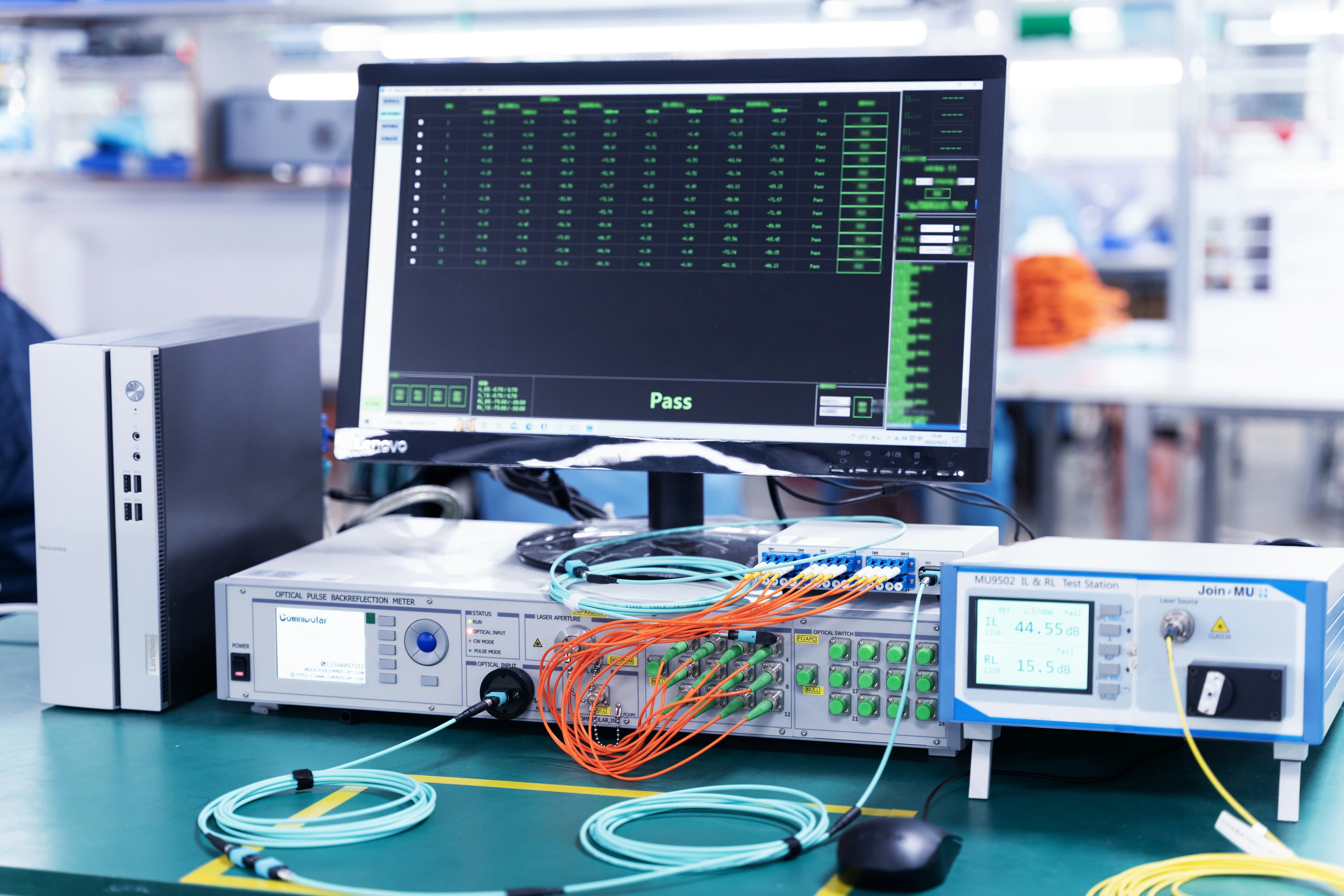
Continuity confirms that an optical path exists. Polarity confirms that each input reaches the intended output. A cable can show low loss and still be unusable when a transmit lane lands on the wrong receive position.
For multifiber assemblies, the most useful record lists the input-to-output position for every fiber or provides a machine-generated map tied to the approved assembly type. Conversion cassettes, harnesses, and mixed-fiber-count assemblies should be reviewed against their controlled drawing rather than a generic A/B/C description.
Layer 3: insertion-loss results
Insertion loss describes the reduction in optical power through the measured path and is reported in decibels. Lower values represent less loss, but the result is meaningful only when the report identifies the test wavelength, fiber type, measurement boundary, reference method, and acceptance limit.
Do not compare two suppliers from the headline loss value alone. A single-ended patch-cord setup and a double-ended installed-link test do not include exactly the same interfaces. Reference leads, connector remating, launch conditions, and measurement uncertainty can also affect the result.
- Numeric result for every required fiber or channel.
- Maximum permitted loss shown on the same report.
- Test wavelength and fiber type.
- Measurement direction and reference method where relevant.
- Clear pass/fail decision tied to the approved limit.
Layer 4: return loss or reflectance
Return loss and reflectance describe reflected optical power using different sign conventions. Optical return loss is commonly shown as a positive value where a higher number indicates less returned power. Reflectance is commonly shown as a negative value where a more-negative number indicates lower reflection.
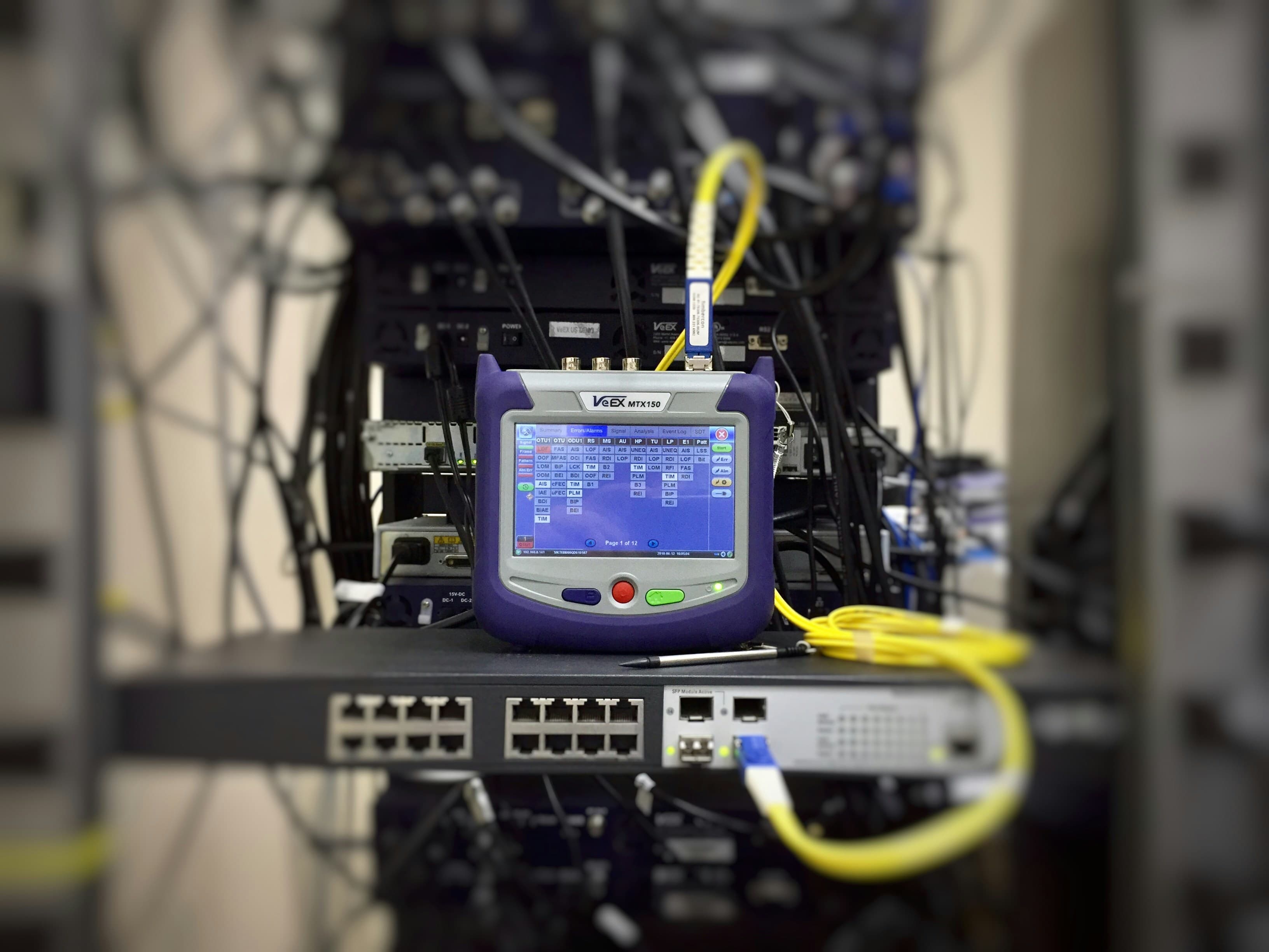
The report should state which quantity is being shown, the wavelength, the test direction, the far-end condition, and the applicable limit. Do not approve a report that labels a column RL but leaves the sign convention or acceptance rule unclear.
Inspection and geometry records are supporting evidence
Connector inspection, end-face geometry, insertion loss, and return loss evaluate different conditions. None should be treated as a universal substitute for the others. The evidence package should include only the checks required by the product specification and should name the criteria used for each decision.
CAIVALE’s current local evidence library includes MT-12APC ferrule 3D interferometer reports and internal batch insertion-loss/return-loss records. These materials can demonstrate that specific samples or batches were measured, but their scope must not be generalized to every product or order.
Traceability connects the report to the delivered cable
A test result becomes useful procurement evidence when it can be retrieved from the physical product identifier. The cable label, report filename, packing list, approval drawing, and production record should share a consistent serial number, lot number, or other controlled reference.
A robust record also identifies the test date, operator or station, test equipment ID, calibration-control reference, and the disposition of any failed or retested channel. Where testing is sampled rather than performed on every assembly and every fiber, the sampling scope should be disclosed.
Buyer review checklist
Use the following questions when reviewing a sample report or production-lot evidence package.
- Does the report identifier match the cable or lot in hand?
- Are connector type, fiber type, length, and polarity shown?
- Is the tested scope every fiber, every assembly, or a stated sample?
- Are wavelength, method, and measurement boundary defined?
- Are numeric IL and RL results shown with their limits?
- Is the input-to-output mapping visible for multifiber assemblies?
- Are test equipment and calibration-control references identified?
- Can the supplier explain cleaning, retest, rework, and rejection rules?
Factory report and field acceptance are different records
A factory report evaluates an assembly under the supplier’s controlled setup before shipment. A field acceptance test evaluates the installed path after transport, pulling, routing, mating, and connection to other components. Shipping and installation can introduce contamination, bends, damage, or port errors that were not present during factory testing.
Keep the factory report as the product baseline and define field testing separately in the commissioning plan. When a link fails, the two records help distinguish a manufacturing issue from an installation or system-level problem.
Related products
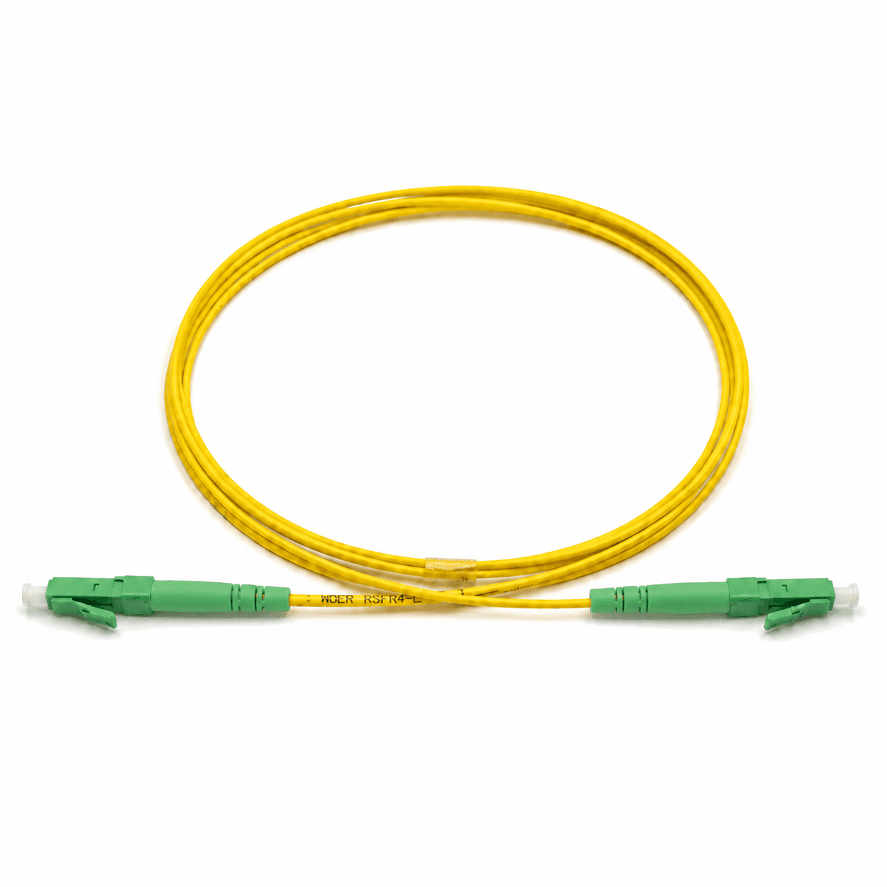
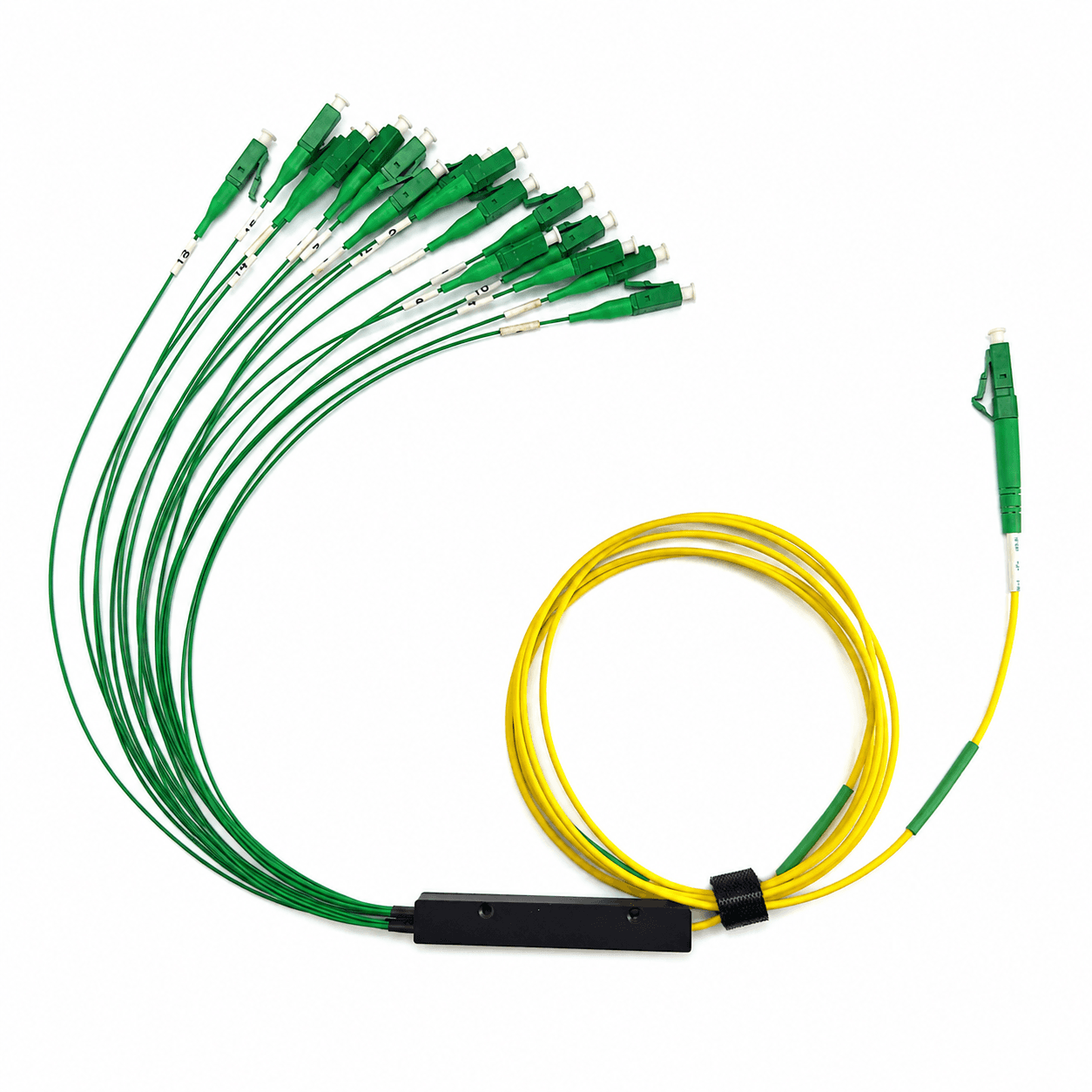
These product families are relevant when turning the article guidance into a defined cable configuration.
Frequently asked questions
Is a pass/fail result enough for cable acceptance?
Usually not. A useful report includes product identity, test method, wavelength, limits, numeric results, and traceability to the delivered assembly or lot.
Are insertion loss and return loss the same measurement?
No. Insertion loss measures forward power reduction, while return loss evaluates optical power reflected toward the source.
Does a clean end-face image prove optical performance?
No. Inspection supports cleanliness acceptance but does not replace insertion-loss, return-loss, continuity, or polarity testing when those checks are required.
Should factory and field test reports match exactly?
They serve different stages. The factory report is the pre-shipment baseline; field testing evaluates the installed link after transport, routing, and mating.
Topics
References and supporting material
- IEC 61300-3-4 — Attenuation measurement for fibre optic interconnecting devices and passive components.
- IEC 61300-3-6 — Return-loss measurement for fibre optic interconnecting devices and passive components.
- CAIVALE local evidence library: internal IL/RL batch records and MT-12APC 3D interferometer reports.
- MPO 12F Trunk Cable Type B Drawing (PDF)
- Browse all CAIVALE product drawings
Need help confirming a fiber specification?
Contact Engineering