
On this page
Key takeaway
Do not approve an MPO channel from an A, B, or C label alone. Verify the complete position map, connector pinning, key orientation, and every component between the transmitter and receiver.
Start by separating three different decisions
MPO cable mapping, connector orientation, and end-to-end channel polarity are related, but they are not interchangeable. Cable mapping describes which position at End A reaches which position at End B. Connector configuration covers guide pins, key orientation, polish, and mating compatibility. Channel polarity asks whether every transmitter reaches the intended receiver after all trunks, adapters, modules, and patch cords are included.
A purchase order that says only “Type B” defines one component behavior, not the completed optical path. The safest specification is a position-by-position drawing that identifies both endpoints and every transformation between them.
How Type A, Type B, and Type C map fibers

For a single-row 12-position MPO assembly, Type A preserves the position numbers from end to end. Type B reverses the full row, so position 1 reaches position 12, position 2 reaches position 11, and so on. Type C swaps adjacent pairs, such as 1 to 2 and 2 to 1.
These definitions explain the cable assembly only. A cassette can remap fibers internally, a duplex patch cord can introduce a crossover, and an adapter determines how connector keys face each other. The finished channel must therefore be traced separately.
- Type A: straight-through position mapping.
- Type B: complete reversal of the fiber row.
- Type C: adjacent-pair crossover.
Connector pinning and key orientation are separate requirements
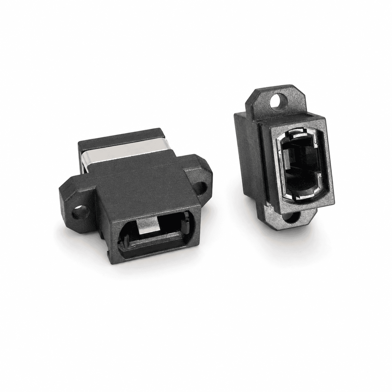
MPO ferrules use guide pins and guide holes for alignment. A normal mating pair requires compatible pinned and unpinned interfaces. Key-up and key-down orientation controls how the numbered positions face each other through an adapter. Neither pinning nor key orientation should be inferred from the polarity label.
For APC multifiber interfaces, the end-face angle and the orientation required by the equipment must also match. Record these items on the drawing instead of relying on connector color or informal male/female terminology.
Trace the complete channel from transmitter to receiver
Draw the channel in physical order: equipment port, patch cord, adapter, trunk, cassette or harness, final patch cord, and destination equipment. Label every connector end, mating point, and fiber-position transformation. Then trace each active transmit lane until it reaches the expected receive lane.
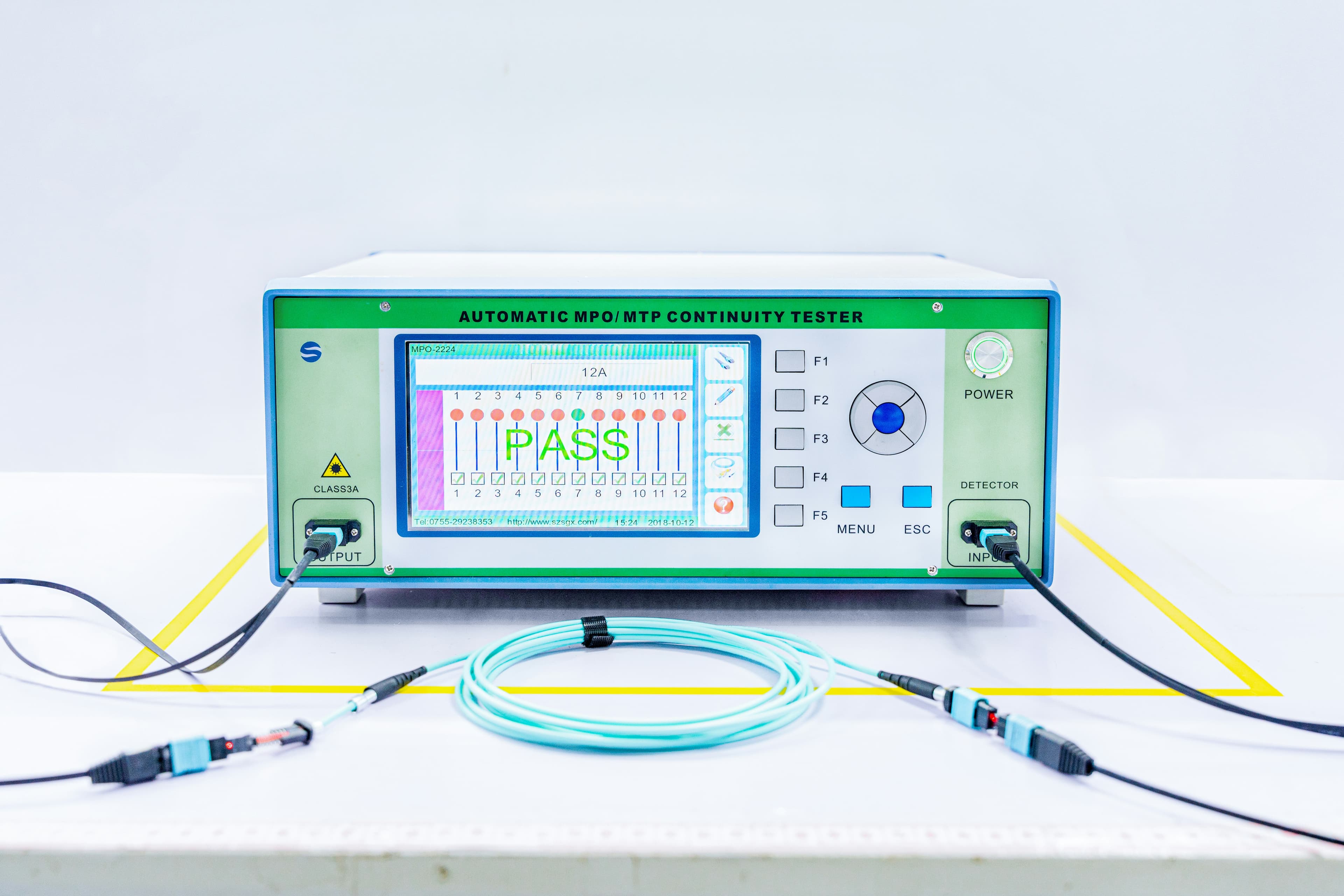
This exercise is especially important for conversion cassettes, breakout harnesses, mixed Base-8 and Base-12 systems, and installations that reuse undocumented components. A low-loss optical path can still be unusable when it terminates on the wrong lane.
Pre-order polarity checklist
Before approving a drawing or releasing a purchase order, confirm the following items as one controlled specification.
- Exact equipment or transceiver interfaces at End A and End B.
- Active fiber positions and required end-to-end Tx-to-Rx map.
- Connector format, fiber count, fiber type, and polish.
- Pinned or unpinned configuration at every MPO mating point.
- Key orientation and adapter orientation.
- Internal mapping of every cassette, module, and harness.
- End labels, port labels, part number, and drawing revision.
- Required polarity, continuity, and insertion-loss evidence.
What the finished evidence package should show
The delivered assembly should be traceable to the approved configuration. A useful evidence package identifies the part number and revision, assembly or lot identifier, End A and End B labels, connector pinning, key orientation, and the approved fiber-position map.
Where project acceptance requires testing, the report should list every fiber or active lane rather than showing only a generic pass statement. The cable label, drawing, test record, and packaging identifier should use the same controlled reference.
Practical buying rule
If a supplier can quote the cable from only “A, B, or C,” the request probably contains unresolved assumptions. A production-ready specification should allow another engineer to reconstruct the entire optical path without asking what the customer meant.
When some information is unavailable, mark it open for engineering confirmation and resolve it on the approval drawing before production begins.
Related products
These product families are relevant when turning the article guidance into a defined cable configuration.
Frequently asked questions
Is Type B always required for parallel optics?
No. The required cable mapping depends on the complete channel, including adapters, modules, patch cords, and the equipment lane assignment.
Can two pinned MPO connectors mate together?
No. A normal MPO mating pair requires one pinned and one unpinned interface, with a compatible adapter and key orientation.
Is cable polarity the same as channel polarity?
No. Cable polarity describes one assembly; channel polarity verifies that every transmitter reaches the intended receiver through the full link.
How should an MPO polarity map be verified?
Use a position-by-position drawing and confirm continuity through the complete representative channel before release or deployment.
Topics
References and supporting material
- ANSI/TIA-568.3-E — Optical Fiber Cabling and Components Standard.
- IEC 61754-7 — Fibre optic interconnecting devices and passive components: MPO connector family.
- MTP® 12F Trunk Cable Type A Drawing (PDF)
- MTP® 12F Trunk Cable Type B Drawing (PDF)
- MPO Key-Up/Key-Down Adapter Drawing (PDF)
- Browse all CAIVALE product drawings
Need help confirming a fiber specification?
Contact Engineering