
On this page
Key takeaway
A production-ready RFQ must define both endpoints, optical mapping, physical construction, labels, testing, quantity, and delivery—or explicitly mark each unknown for engineering confirmation.
Why two connector names and a length are not enough
A custom fiber assembly affects optical performance, equipment compatibility, rack routing, installation labor, labeling, testing, packaging, and project delivery. When the RFQ leaves these decisions open, suppliers either quote different assumptions or return a price that changes after technical review.
A production-ready request does not need to solve every engineering question in advance. It must identify known requirements, mark unknown items clearly, and provide enough context for the supplier to recommend and document the remaining choices.
1. Define the application and both endpoints
State what the assembly connects, where it will be installed, and whether it will be routed once or repeatedly moved. List the exact equipment manufacturer and model at End A and End B whenever possible. Equipment documentation is often the most reliable source for connector format, polish, active lanes, and interface pinning.
Include environmental requirements that can change the construction: indoor or outdoor use, plenum or riser space, low-smoke requirements, moisture, flexing, crush risk, temperature, cabinet space, and minimum routing radius.
2. Specify the optical interfaces
Define the connector format at each end, such as LC, SC, or MPO, and state UPC or APC polish. For MPO assemblies, specify pinned or unpinned configuration, key orientation, fiber count, and the complete polarity or position map. Do not assume that color or an A/B/C label defines every interface requirement.

Specify the fiber type required by the equipment and installed plant, such as OS2, OM3, or OM4. If bend-insensitive performance, a particular standard, or an approved fiber manufacturer is mandatory, include it explicitly.
3. Define fiber count, architecture, and polarity
State both the total fiber count and how fibers are grouped into connectors or breakout legs. A 24-fiber assembly might use two 12-position interfaces, three 8-fiber groups, or another mapping. These are not interchangeable even when the total fiber count is the same.
Attach a position-by-position map for conversion harnesses, cassettes, and nonstandard breakouts. Label End A, End B, each branch, and each destination port. The approved drawing should become the single reference for production, labels, inspection, and testing.
4. Define the physical construction
Give the nominal length, unit, tolerance, and measurement reference. For a breakout assembly, define whether the overall dimension is measured connector-tip to connector-tip, to the transition point, or by another controlled method.
Specify cable construction, outside diameter if routing space is limited, breakout-leg count and length, stagger pattern, furcation size, pulling eye or pulling sock, pulling direction, protection for fanout legs, and any armor or crush requirement.
5. Treat labeling and packaging as part of the design

Define label text, End A and End B convention, rack and port sequence, barcode or QR requirements, label position, and packaging order. For project kits, packaging should follow the installation sequence so technicians do not need to sort dozens of nearly identical assemblies on site.
Ask for the cable label, approval drawing, test report, and packing list to share the same assembly or lot identifier. This creates practical traceability between the approved specification and the delivered product.
6. State optical acceptance and documentation requirements
Specify the required insertion-loss limit, return-loss requirement when applicable, test wavelength, measurement boundary, and reference method. Limits should come from the approved channel design or equipment requirement rather than an unqualified “low loss” description.
List the evidence that must accompany the order. Depending on the project, this may include per-fiber continuity, polarity, insertion-loss data, return-loss data, assembly or lot identifiers, test date, equipment or station ID, and a disclosed sampling scope.
- Per-fiber or per-channel numeric results where required.
- Acceptance limit shown alongside each result.
- Test wavelength and method or reference condition.
- Assembly serial number or controlled lot identifier.
- Report file naming that matches cable and packaging labels.
7. Include quantity, spares, delivery, and commercial conditions
Separate prototype quantity, production quantity, and spare quantity. State whether partial shipments are acceptable, the required-on-site date, destination, requested Incoterm, packaging constraints, quote-validity requirement, and any vendor-onboarding documents needed before release.
When a field is unknown, write “open for recommendation” rather than guessing. The supplier can then record the proposed value and any exception on the approval drawing or quotation.
What should happen after the RFQ is submitted
A controlled custom process should create four connected records: a requirements review that resolves questions, an approval drawing that freezes configuration and revision, a production record tied to that revision, and acceptance evidence tied to the delivered assemblies.
Before production, check that the quotation, drawing, label schedule, and test scope describe the same product. A detailed RFQ creates value only when its requirements remain traceable through manufacture and delivery.
Related products
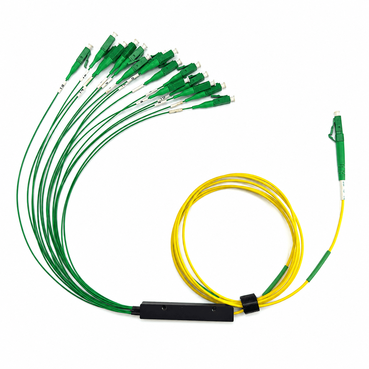
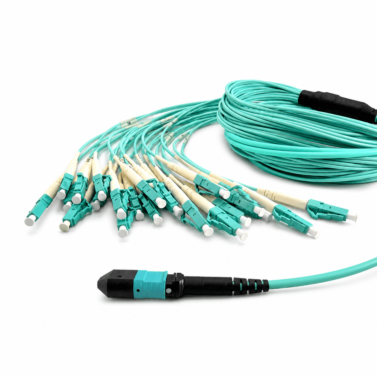
These product families are relevant when turning the article guidance into a defined cable configuration.
Frequently asked questions
What information is essential in a custom fiber RFQ?
Define both endpoints, connector interfaces, fiber type, count, polarity, construction, length, labeling, testing, quantity, and delivery requirements.
What if some cable specifications are unknown?
Mark them open for engineering recommendation and require the selected values to be recorded on the approval drawing before production.
Should polarity be written only as Type A, B, or C?
For multifiber and conversion assemblies, include a position-by-position map because the letter alone may not define the complete channel.
When should production begin?
Production should begin only after the quotation, approval drawing, label schedule, and test scope describe the same controlled configuration.
Topics
References and supporting material
- IEC 61300 series — Basic test and measurement procedures for fibre optic interconnecting devices and passive components.
- CAIVALE internal RFQ and production-release requirements should be confirmed on the final approval drawing.
- LC UPC–LC UPC Simplex Patch Cable Drawing (PDF)
- MPO to 8LC OM3 Harness Cable Drawing (PDF)
- Browse all CAIVALE product drawings
Need help confirming a fiber specification?
Contact Engineering