On this page
Key takeaway
An insertion-loss value is comparable only when wavelength, reference method, launch condition, measurement boundary, and acceptance limit are defined.
What insertion loss measures
Insertion loss is the reduction in optical power caused when a component or cable assembly is inserted into an optical path. It is expressed in decibels and can include losses from fiber attenuation, connector pairs, splices, splitters, and other passive components in the measured path.
For a finished cable assembly, the result is meaningful only when the measurement method, wavelength, reference method, launch conditions, and connector configuration are defined. Two laboratories can test the same cable and obtain different values if those conditions are not controlled.
Use the light-source and power-meter method correctly
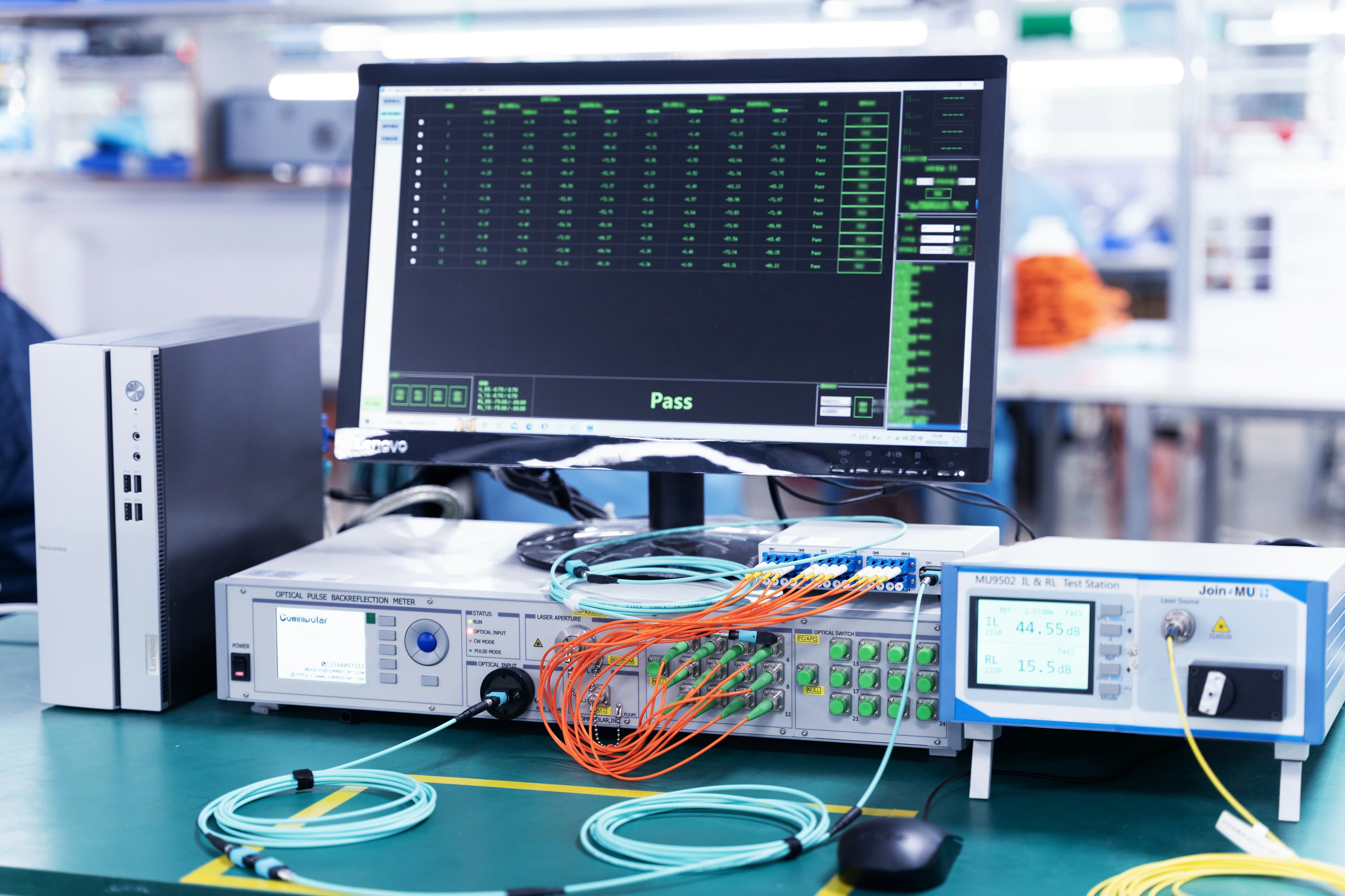
A common setup uses a stabilized light source and optical power meter, often combined as an optical loss test set. The system first establishes a reference power level. The device under test is then inserted between the reference leads, and the change in received power is reported as insertion loss.
IEC 61300-3-4:2023 describes methods for measuring attenuation of optical components. Installed cable plants may use other application-specific procedures, so the method should match whether the subject is a connector, patch cord, trunk assembly, or end-to-end link.
Reference conditions control the result
The zero-reference procedure determines which connections are included in the final result. A one-cord, two-cord, or three-cord reference can produce a different measurement boundary. The report must state the method used so the result can be interpreted and reproduced.
Reference cords should be clean, stable, compatible with the interface under test, and verified before use. Worn adapters, contaminated connectors, source drift, and repeated remating can increase measurement uncertainty.
- Record the test wavelength and source type.
- Identify the reference method and reference-cord interfaces.
- Allow the source and instruments to stabilize before testing.
- Inspect every test interface before establishing the reference.
- Re-establish the reference when equipment or reference leads change.
Choose wavelengths for the actual fiber system
Test wavelengths should correspond to the fiber type and intended application. Multimode assemblies are commonly evaluated at 850 nm and, when required, 1300 nm. Single-mode assemblies are commonly evaluated at 1310 nm and, when required, 1550 nm. Project specifications or equipment requirements remain the controlling source.
Multimode results are especially sensitive to launch conditions. An uncontrolled launch can overfill or underfill the fiber modes and produce results that do not represent the installed system. The specified method should define the launch requirement rather than naming only a wavelength.
Set acceptance limits from the complete channel
A universal pass/fail number is not appropriate for every assembly. The acceptance limit should come from the product specification or channel loss budget, including mated connector pairs, fiber length, splices, splitters, and required engineering margin.
For short patch cords, connector performance normally dominates the measurement. For longer trunks and installed links, fiber attenuation and additional connection points become more significant. Tightly budgeted systems may require lower-loss components and stricter limits than general-purpose links.
Specify a useful test report
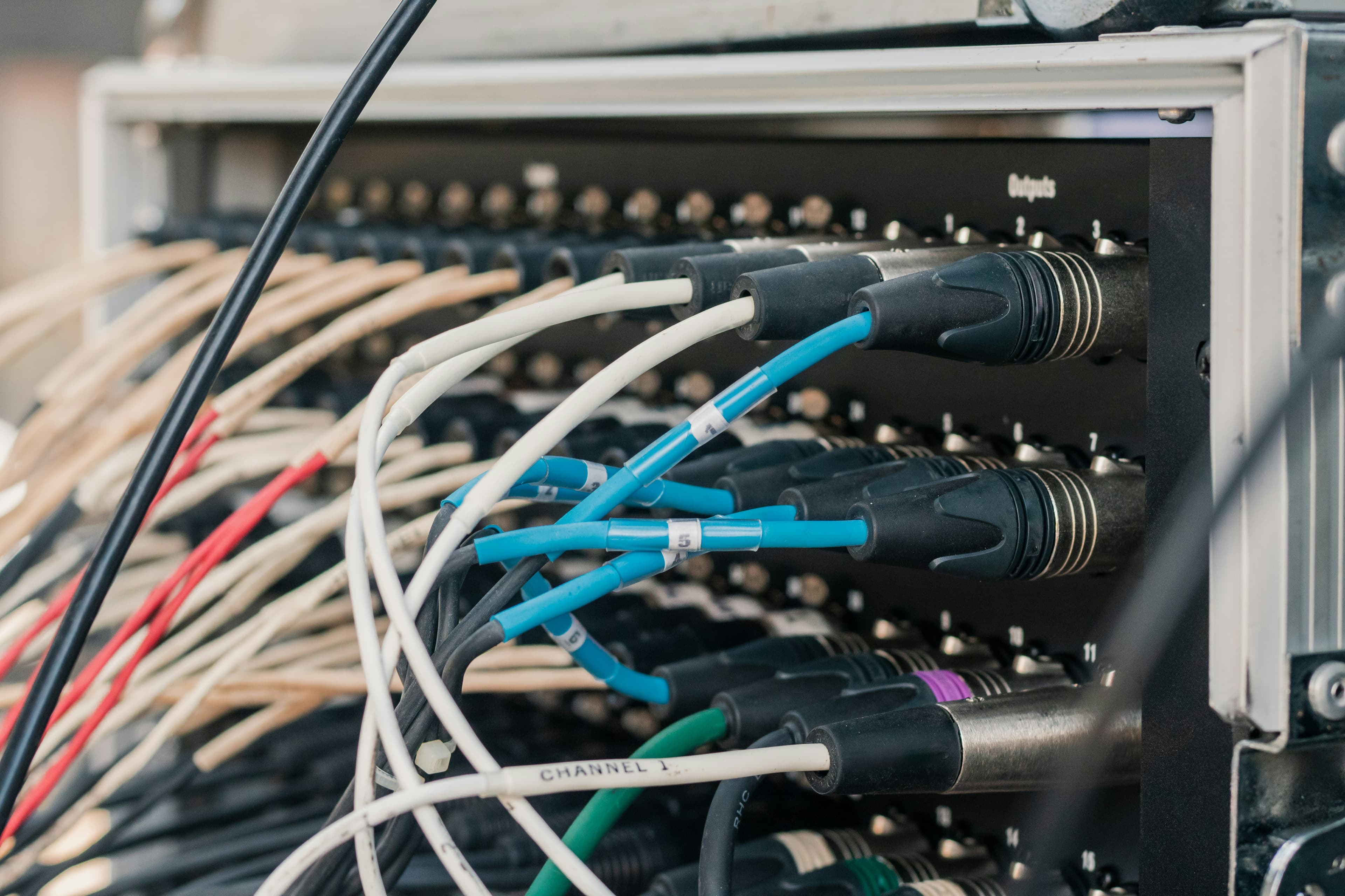
A useful report makes every measured fiber traceable to the physical product. It should identify the assembly ID, fiber position, direction, wavelength, measured loss, acceptance limit, result, instrument, reference method, and test date.
For multifiber assemblies, combine insertion-loss results with polarity and continuity records. Add end-face inspection records when required so optical performance and cleanliness evidence remain distinguishable. This documentation is more useful than a certificate that only states the product passed internal inspection.
Related products
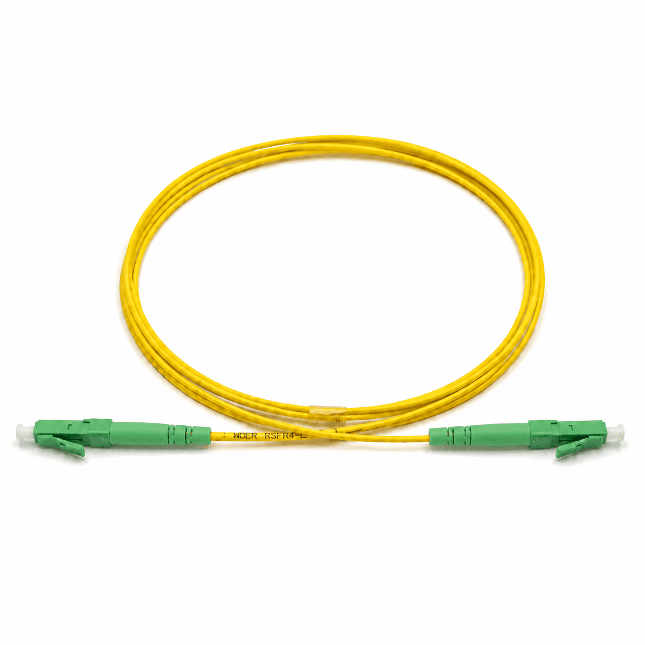
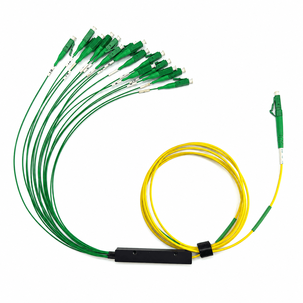
These product families are relevant when turning the article guidance into a defined cable configuration.
Topics
References and supporting material
Need help confirming a fiber specification?
Contact Engineering