On this page
Key takeaway
Specify return loss with the polish, wavelength, method, direction, measurement boundary, and limit; “low reflection” alone is not an acceptance requirement.
What return loss tells you
Optical return loss describes the ratio between power entering a device and the total power reflected toward the source. It is expressed in decibels. A higher positive return-loss value indicates less reflected power and is generally preferred.
Return loss is not insertion loss. Insertion loss measures forward power reduction through a component or link, while return loss evaluates reflected power traveling in the opposite direction. A connection can meet one requirement and fail the other.
Return loss and reflectance use opposite conventions
Reflectance describes reflected power at an individual event and is normally expressed as a negative decibel value. Return loss describes the incident-to-reflected power ratio and is normally expressed as a positive value. For the same event, a reflectance of −50 dB corresponds conceptually to a return loss of 50 dB.
Because specifications may use either term, procurement documents should name the parameter, sign convention, method, wavelength, and acceptance limit. This avoids treating a more-negative reflectance value as a worse result when it represents lower reflection.
Why UPC and APC polish matter
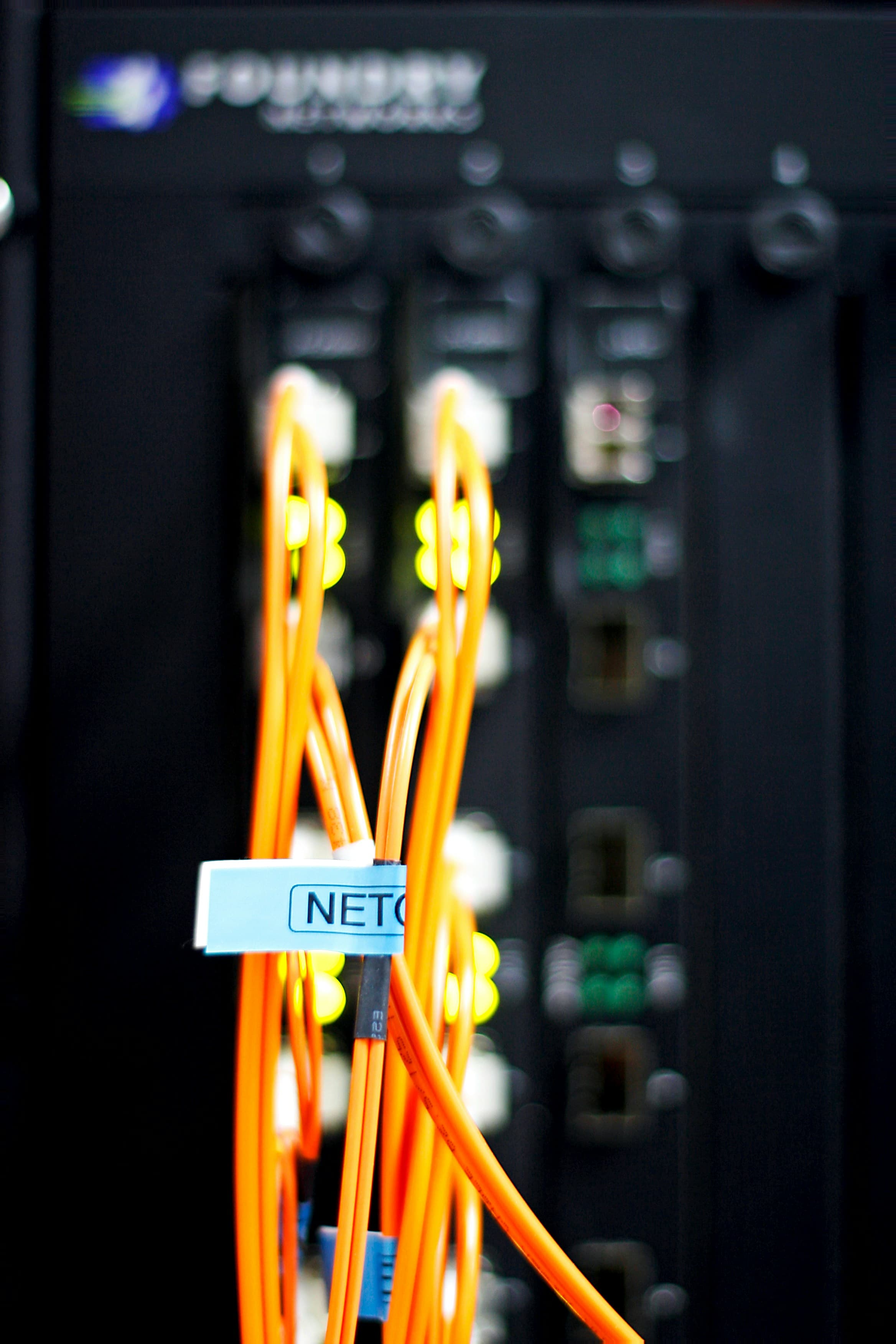
Physical-contact connector designs reduce the glass-to-air gap that would otherwise create a strong Fresnel reflection. UPC connectors use an improved convex physical-contact polish, while APC connectors use angled geometry that directs reflected light away from the fiber core.
APC interfaces are commonly selected where low back reflection is important, including some analog, RF-over-fiber, PON, sensing, and reflection-sensitive systems. UPC and APC connectors must not be mated together because their end-face geometries are incompatible.
Identify common causes of reflection
Reflection can rise because of contamination, an air gap, poor end-face geometry, damaged fiber, incompatible polish types, or unstable physical contact. Cleaning may correct contamination, but it cannot repair geometry or alignment problems.
For multifiber connectors, ferrule geometry, fiber height, and mating conditions can affect many channels at once. Review failures together with end-face images, insertion-loss results, and interferometer data when available.
- Dust, oil, or residue within the optical contact area.
- Scratches, pits, cracks, or chipped fiber near the core.
- UPC-to-APC or otherwise incompatible mating interfaces.
- Excessive air gaps or insufficient physical contact.
- Poor radius, apex offset, fiber height, or ferrule geometry.
Measure return loss with a defined method
IEC 61300-3-6 defines procedures for measuring the return loss of a fiber-optic device under test. Practical systems may use an optical return-loss meter, optical continuous-wave reflectometer, or another method appropriate to the product and measurement boundary.
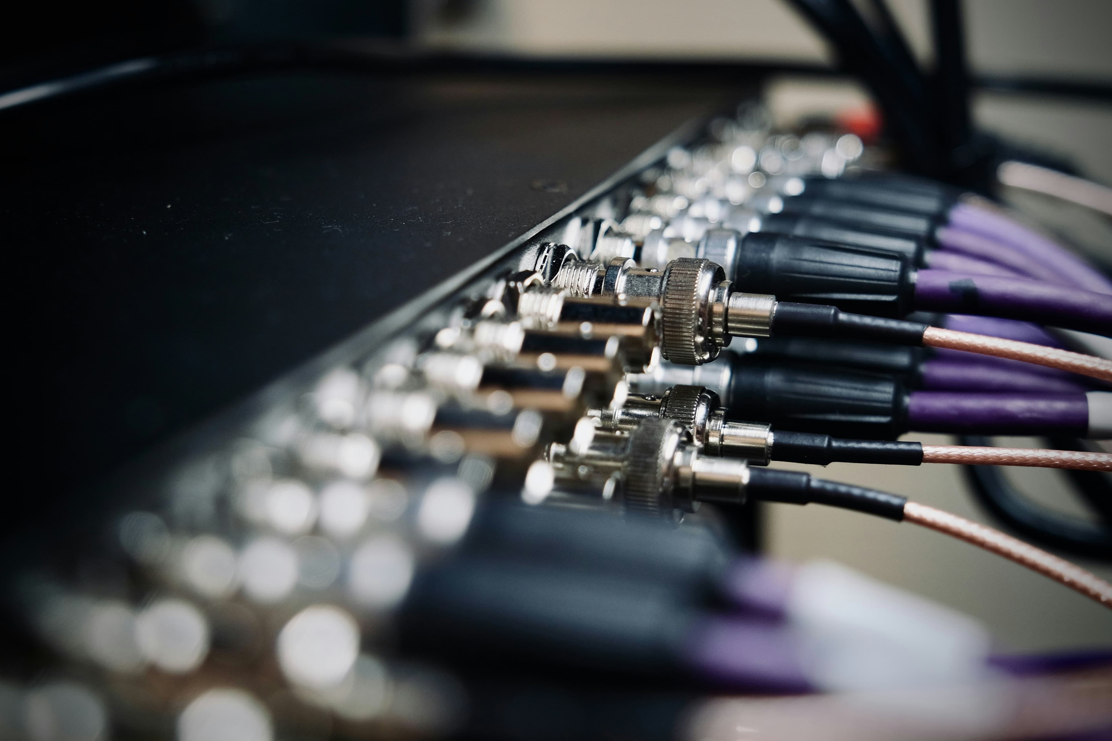
Reference quality and cleanliness matter. The method must separate reflection associated with the device under test from reflections in the reference leads, adapters, and instrument interface. Direction can also matter for asymmetric assemblies or links with multiple events.
Write a reliable return-loss requirement
Do not specify only “low reflection.” State the connector type and polish, fiber type, wavelength, measurement method, minimum return loss or maximum reflectance, test direction, and reporting requirement. Clarify whether the limit applies to each connector event, each assembly, or the combined link.
Targets should come from the transceiver, network, or project specification rather than a generic marketing grade. The supplier can then select the construction, polishing process, inspection criteria, and test plan needed to demonstrate compliance.
Related products
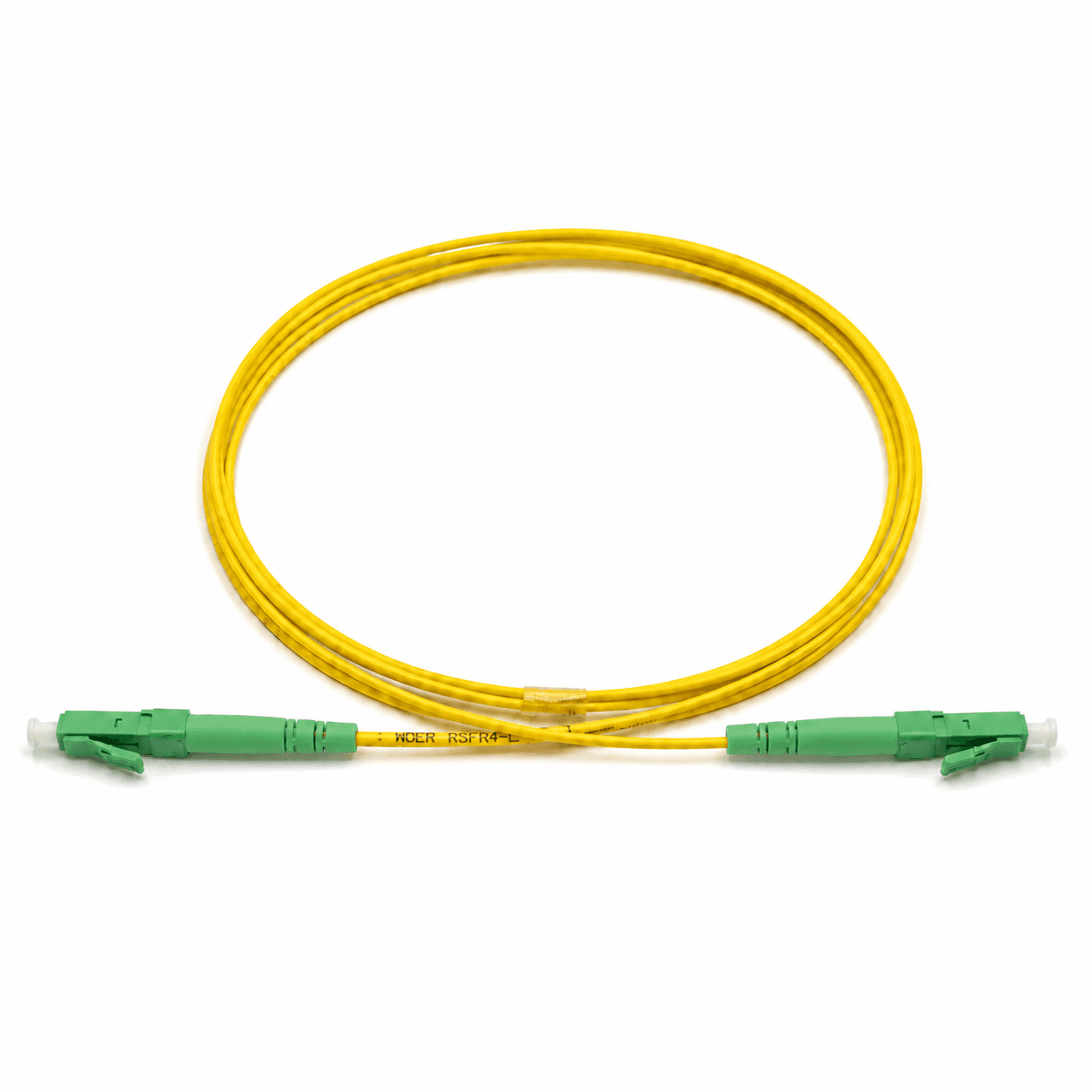
These product families are relevant when turning the article guidance into a defined cable configuration.
Topics
References and supporting material
Need help confirming a fiber specification?
Contact Engineering