
On this page
Select an MTP/MPO cable from the complete optical path—not from connector name alone. Define what each end mates with, then approve fiber count, fiber type, gender, position mapping, construction, dimensions, and acceptance evidence as one controlled configuration.
Eight decisions to make before quotation
Work through these decisions in order. Each answer constrains the next one and reduces the assumptions that would otherwise appear in a quotation or approval drawing.
Start with the link, not the cable name
Draw the channel in physical order: equipment port, patch cord, adapter, trunk, cassette or harness, and destination equipment. Identify what each cable end mates with. The same MPO interface can require a different fiber count, gender, or polarity when its position in the channel changes.
Review point: If the link includes existing cassettes or adapters, record their port mapping and key orientation before selecting the new assembly.
Choose trunk or breakout construction
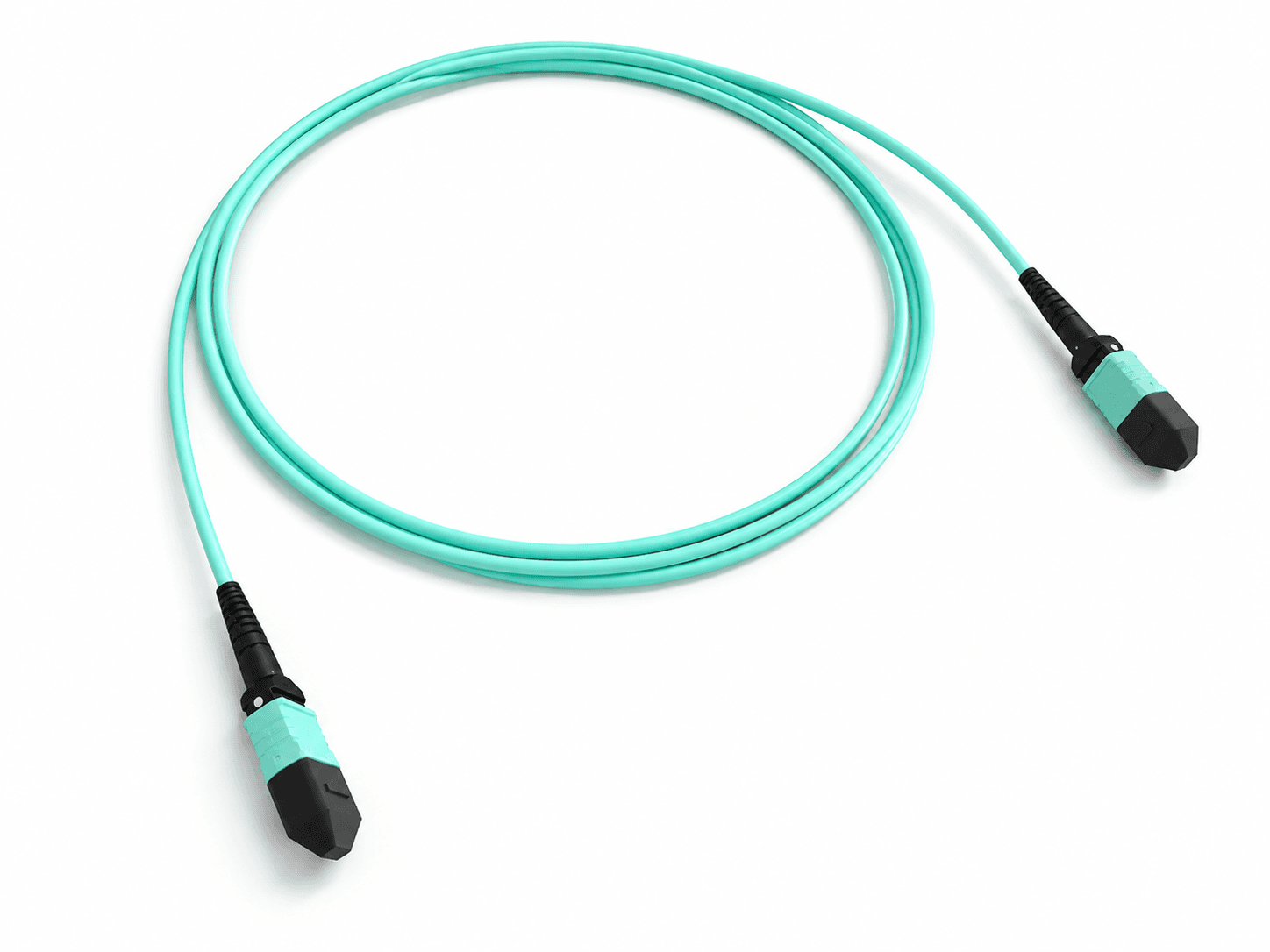
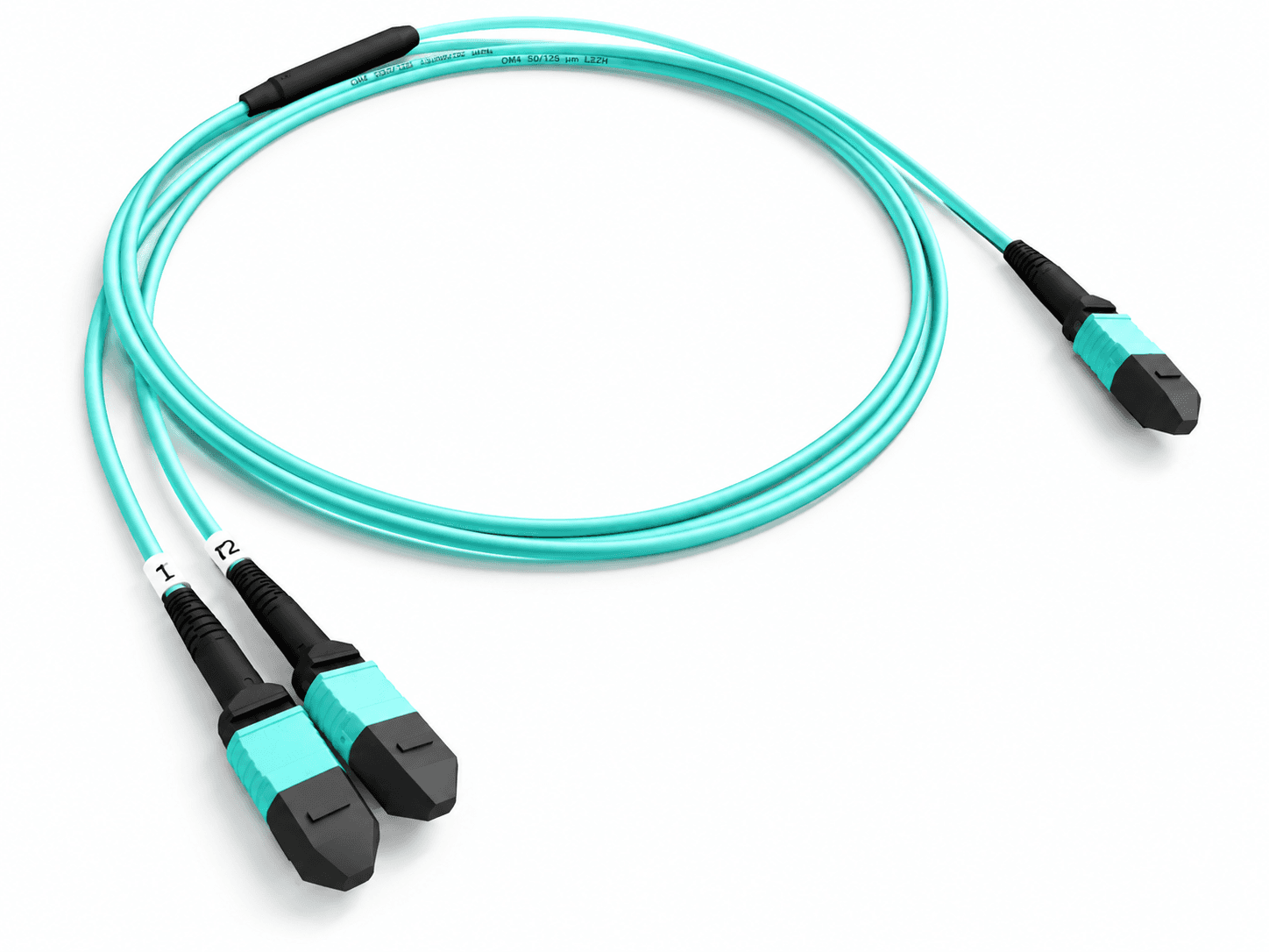
Use an MTP/MPO-to-MTP/MPO jumper or trunk when both endpoints require multifiber interfaces. Use a hydra or harness when one multifiber connector must break out to LC, SC, FC, ST, MU, E2000, or MT-RJ interfaces. Pulling assemblies add installation protection for pathway routing.
Review point: For a breakout, define both total length and fan-out length; those dimensions solve different installation constraints.
Confirm fiber count and cabling architecture
Match the active positions to the transceiver, cassette, and installed backbone. The current product paths include 12F and 24F configurations as well as higher-count trunk constructions. Do not assume that every position in a connector is active or that a Base-12 backbone automatically fits an 8-fiber application without a documented mapping plan.
Review point: Record the active fiber positions whenever a conversion, unused position, or mixed Base-8/Base-12 channel is involved.
Select fiber type from the system requirement
Choose single-mode or multimode from the transceiver specification, required reach, installed infrastructure, and project standard. Available configuration paths include single-mode G652D and G657 variants and multimode OM2, OM3, and OM4. Cable color can help identify a build, but the controlled specification must state the fiber type.
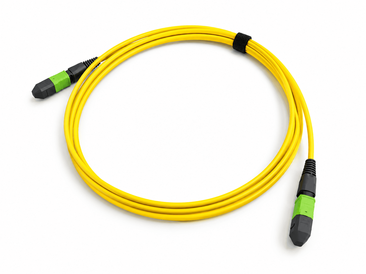
Review point: Do not approve a fiber type from color alone; labels, order code, and test records should agree.
Define both mating interfaces and connector gender
A pinned connector uses guide pins; an unpinned connector uses guide holes. A normal mating pair requires compatible interfaces, but the correct choice depends on equipment ports, cassettes, adapters, and the rest of the channel. Specify End A and End B separately rather than assuming one standard combination.
Review point: Pinned or unpinned gender, key orientation, and polarity are separate requirements and should appear separately on the drawing.
Approve polarity for the complete channel
Type A preserves position order, Type B reverses the row, and Type C swaps adjacent pairs for a single-row 12-position assembly. Those labels describe cable mapping, not the finished Tx-to-Rx path. Confirm every trunk, adapter, module, harness, and patch cord together.
Review point: For project-specific links, approve a position-by-position map rather than relying on the letter alone.
Finish the mechanical specification
Define ribbon or round construction, jacket requirement, color, length measurement reference, breakout dimensions, and installation protection. Current options include OFNR, OFNP, LSZH, Hytrel, and project-specific jacket review, with pulling eye, pulling grip, or pulling sock options on applicable trunks.
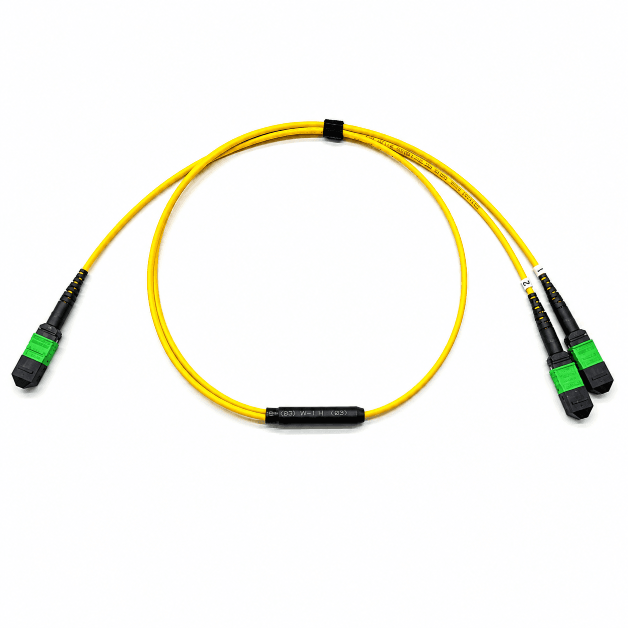
Review point: State whether the quoted length is connector-end to connector-end and identify any required dimensional tolerance.
Define performance evidence before quotation
State the required insertion-loss grade, test wavelength, acceptance limit, channel scope, and report format. IL/RL reports are available on relevant product paths upon request, but the requested evidence must be aligned with the ordered configuration and project acceptance criteria.
Review point: “Low loss” is not a complete requirement. Tie the component limit to the link loss budget and the selected test method.
MTP/MPO selection table
Use this table as a review aid, not as an automatic product recommendation. Equipment documentation and the complete channel remain the controlling inputs.
| Decision | Available path | Question to answer |
|---|---|---|
| Assembly structure | MTP/MPO trunk or jumper; hydra or harness; pulling trunk | What does each end connect to? |
| Fiber count | 12F / 24F and higher-count trunk paths; project-dependent breakout counts | Which positions are active in the complete link? |
| Fiber type | G652D / G657 variants; OM2 / OM3 / OM4 | What do the transceiver and installed system require? |
| Connector gender | Pinned or unpinned at End A and End B | What interface mates at each endpoint? |
| Polarity | Type A / Type B / Type C | What end-to-end Tx-to-Rx map is required? |
| Cable and jacket | Ribbon or round; OFNR / OFNP / LSZH / Hytrel / other review | Where and how will the cable be installed? |
| Dimensions | Total length, fan-out length, breakout arrangement | What are the measurement reference and routing constraints? |
| Evidence | Insertion loss, return loss, continuity, polarity, labeling | Which results and traceability fields must be delivered? |
Six common specification mistakes
Ordering “an MPO cable”
The description does not define fiber count, gender, polarity, construction, or length.
Treating gender as polarity
Guide pins control physical alignment; polarity controls fiber-position mapping.
Checking only one cable
Channel polarity depends on every adapter, cassette, harness, and patch cord in the path.
Choosing by jacket color
Color is an identifier, not a controlled substitute for fiber and jacket specifications.
Requesting “low loss” only
The supplier still needs a performance grade, limit, wavelength, method, and evidence scope.
Leaving length undefined
Total length and breakout length require an agreed measurement reference.
MTP/MPO RFQ Checklist
Mark unresolved items as open for engineering review. The selected values should be recorded on the final quotation or approval drawing before production.
- Application and link diagram
- Assembly structure
- End A interface and gender
- End B interface and gender
- Fiber count and active positions
- Fiber type
- Polarity or position map
- Cable construction and jacket
- Total and fan-out lengths
- Installation protection
- Test and report requirements
- Labels and packaging
- Quantity and destination country
- Required delivery date
Related products
These product families are relevant when turning the article guidance into a defined cable configuration.
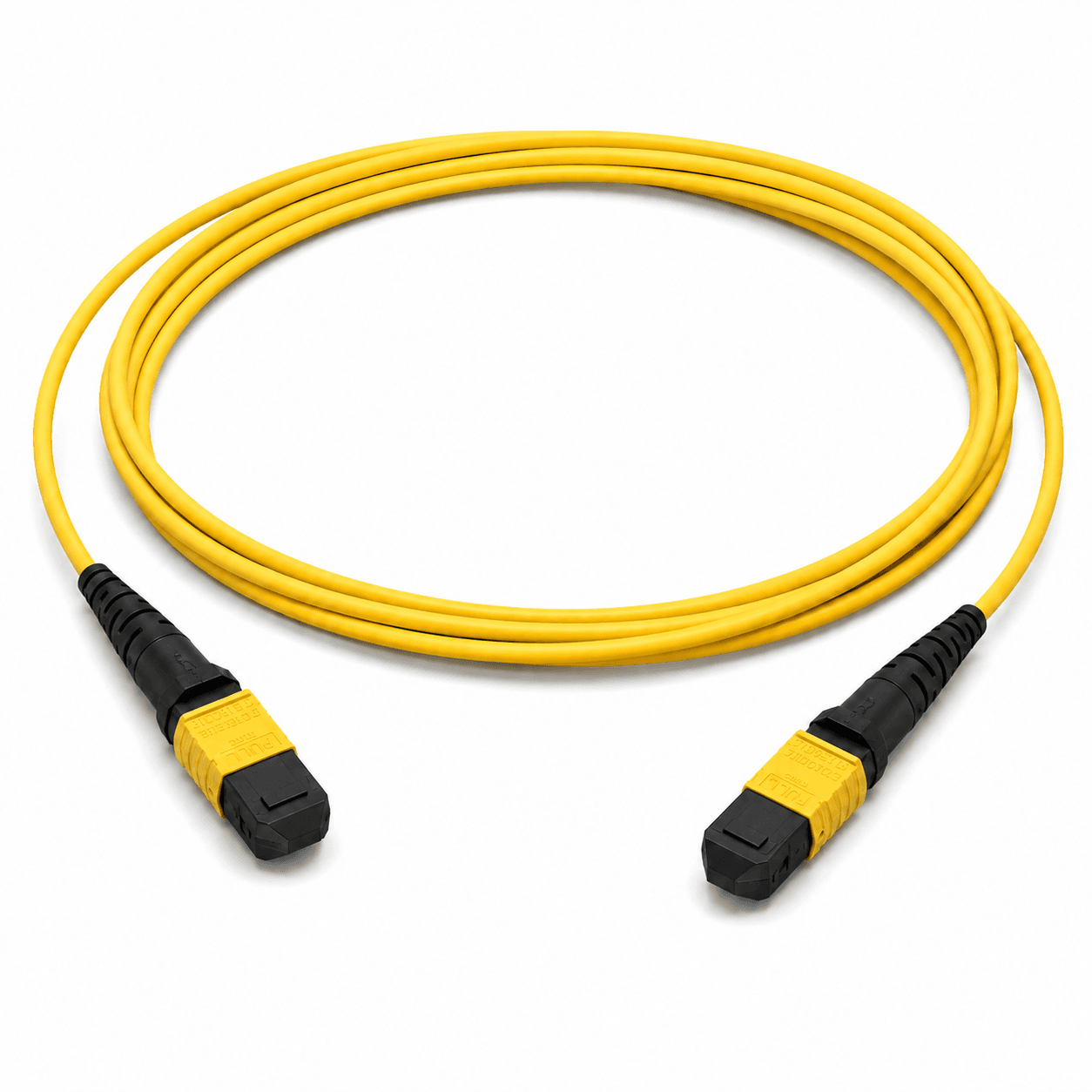
Custom MTP®/MPO Trunk Cable Assemblies
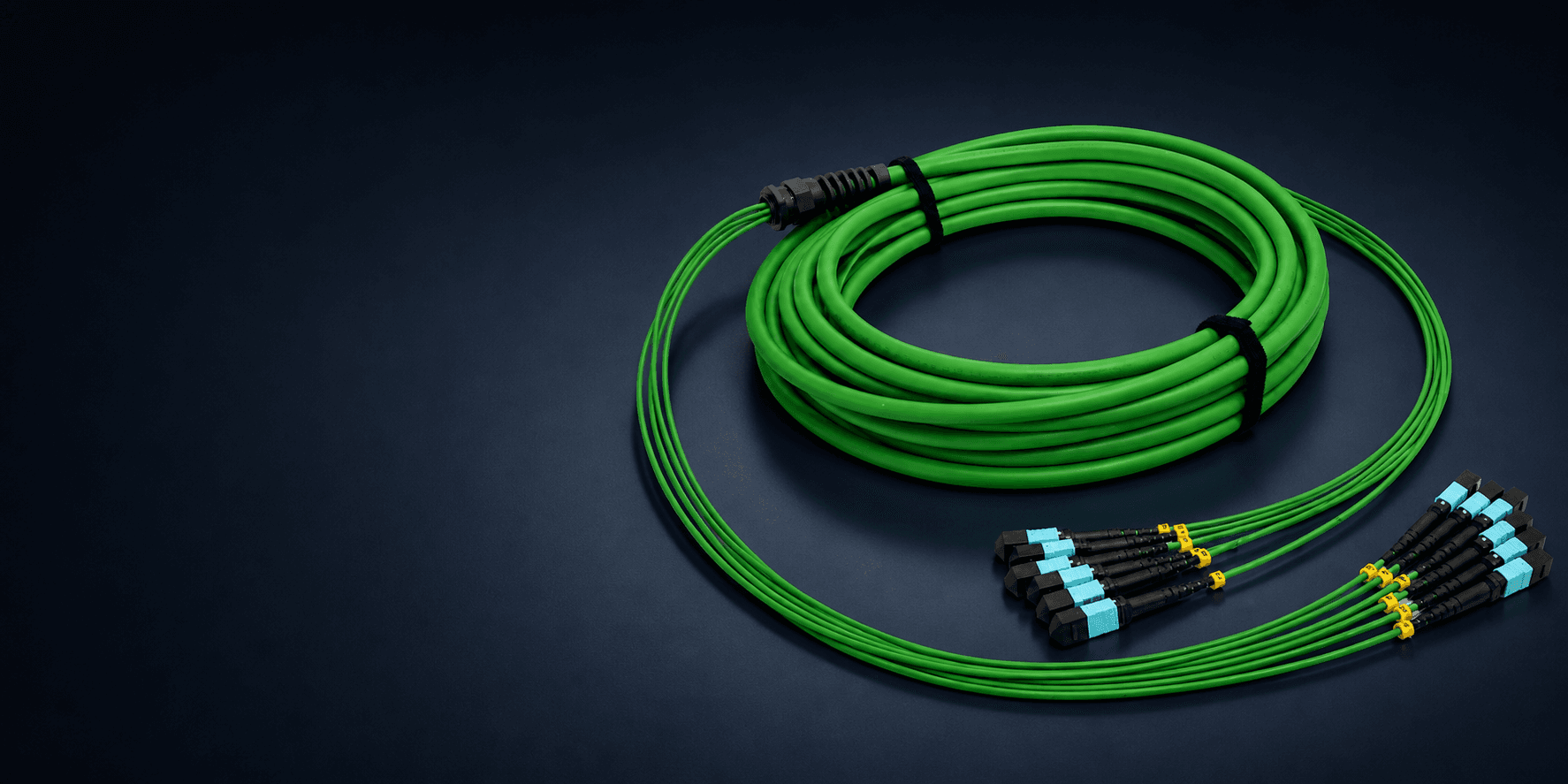
MTP® or MPO standard jumper and trunk cable assemblies with standard, pulling eye, pulling grip, or pulling sock installation options.
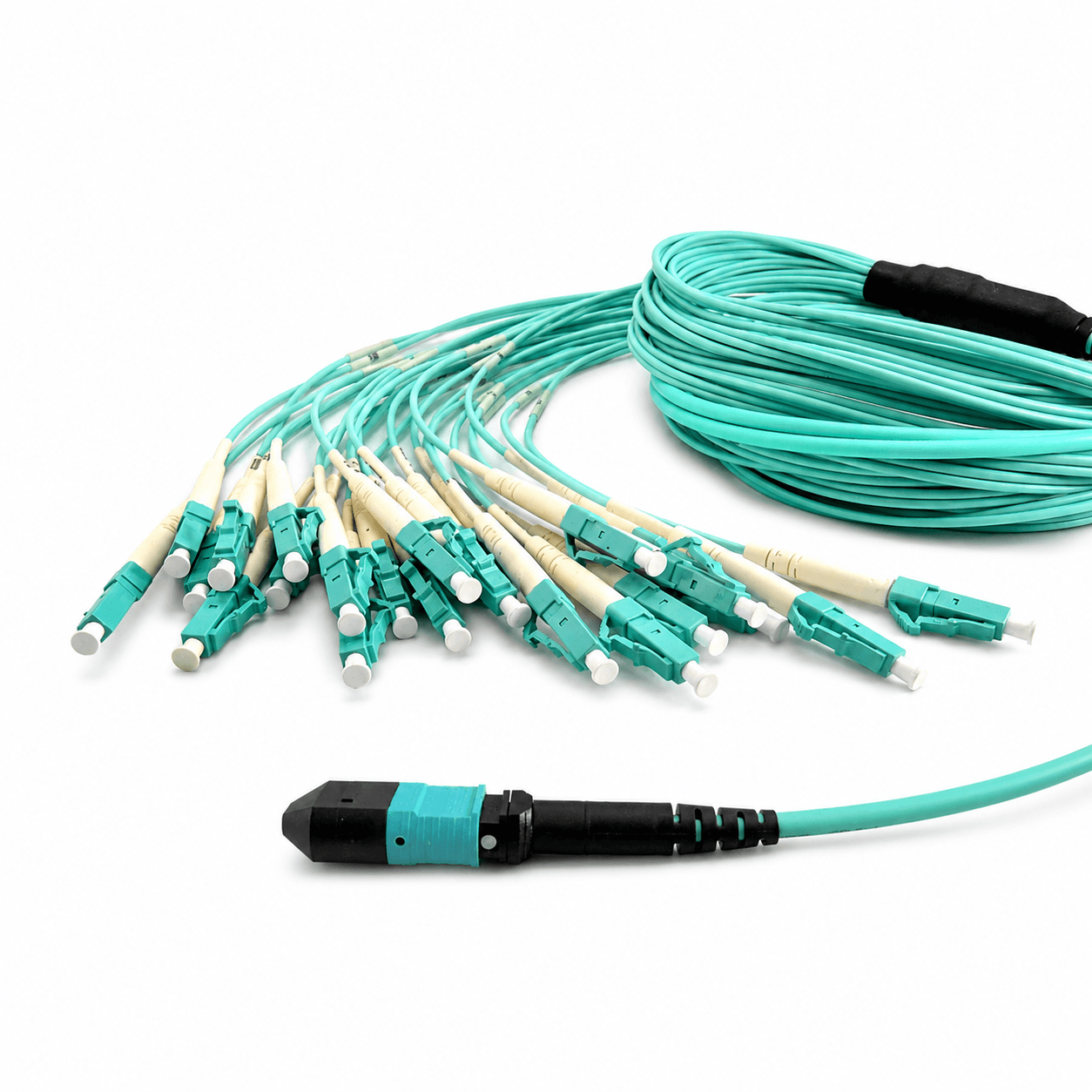
MTP® or MPO Hydra & Harness
MTP® or MPO hydra and harness breakout cable assemblies to LC, SC, FC, ST, MU, E2000, or MT-RJ connectors.
Frequently asked questions
What is the difference between MTP® and MPO?
MPO is the generic multifiber push-on connector interface. MTP® is a registered connector brand from US Conec within the MPO format. The interface name alone does not define performance grade, fiber count, gender, or polarity.
When should I use a trunk instead of a hydra or harness?
Use a trunk or jumper when both ends require MTP/MPO interfaces. Use a hydra or harness when one multifiber interface must break out to LC, SC, FC, ST, MU, E2000, or MT-RJ connectors.
How do I choose pinned or unpinned connectors?
Inspect the mating interface at each endpoint. A normal MPO mating pair requires compatible pinned and unpinned interfaces, but the correct assembly configuration depends on equipment, adapters, cassettes, and the complete channel.
Can I select Type A, B, or C from the cable alone?
No. Cable mapping is only one part of channel polarity. Trace the equipment ports, patch cords, adapters, trunks, cassettes, and harnesses from transmitter to receiver before approving the assembly.
What information is needed for a quotation?
Provide the assembly structure, both connector interfaces and genders, fiber count and type, polarity, cable and jacket, total and fan-out lengths, installation option, testing, labeling, quantity, and destination country.
References and supporting material
- ANSI/TIA-568.3-E — Optical Fiber Cabling and Components Standard.
- IEC 61754-7 — Fibre optic interconnecting devices and passive components: MPO connector family.
- MPO Polarity Explained: Type A, Type B, and Type C
- Base-12 to Base-8 Fiber Migration: Three Practical Paths
- Custom Fiber Assembly RFQ Checklist
- MTP® 12F Trunk Cable Type A Drawing (PDF)
- MTP® 12F Trunk Cable Type B Drawing (PDF)
- MPO Key-Up/Key-Down Adapter Drawing (PDF)
- Browse all CAIVALE product drawings