
On this page
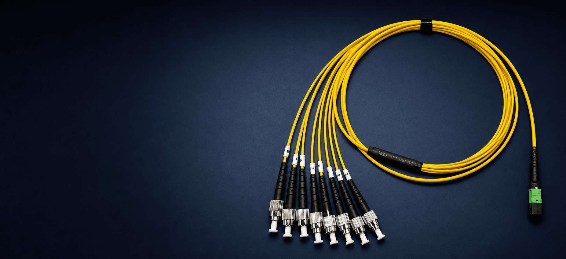
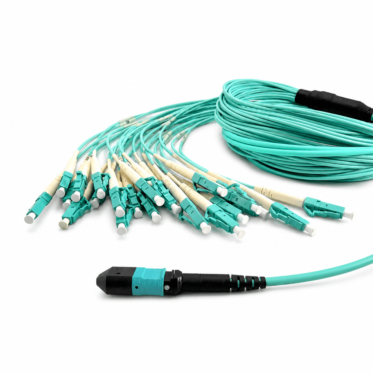
Use a breakout assembly when one MTP/MPO interface must become multiple individually addressable ports. Choose the structure from the two endpoints, then control branch count, port mapping, fan-out dimensions, and identification on one approved drawing.
An MTP/MPO breakout assembly is not selected by connector count alone. It sits between two different connection systems: a compact multifiber interface on one side and a set of separately routed ports on the other. The assembly has to translate both the optical position map and the physical equipment layout.
That is why two cables that look similar in a catalog can be incompatible in service. They may use different active positions, branch sequences, connector formats, leg lengths, or label conventions. A useful selection process therefore begins with the complete link and ends with an approved drawing—not with the words harness or hydra.
What does each end connect to?
Product names come after the physical link is understood.
Multifiber interface
Document equipment or adapter, MTP/MPO gender, active fiber positions, and key orientation.
Individually routed ports
Define connector type, simplex or duplex format, port sequence, physical spacing, and reach.
If both ends remain MTP/MPO, the link normally belongs in the trunk category rather than the breakout category.
Three terms, one specification problem
Market terminology overlaps. Treat the name as a starting point and the drawing as the controlled definition.
Harness
Commonly describes one MTP/MPO interface breaking out to multiple simplex or duplex equipment-side connectors.
Hydra
Often used for a purpose-built multifiber breakout with individually routed legs, but supplier definitions are not universal.
Fan-out
Describes the physical transition from the main cable into protected individual legs; it may appear in either a harness or hydra assembly.
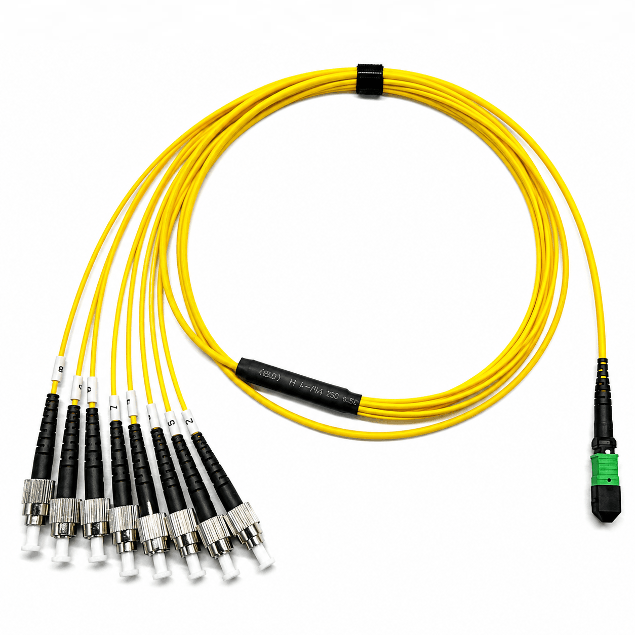
These terms are useful for navigation, but none of them defines a manufacturable assembly. One supplier may call any MTP/MPO-to-discrete-connector cable a hydra, while another reserves that name for long, independently protected branches. Harness may describe duplex LC legs in one catalog and a wider range of simplex connectors in another.
For quotation and approval, replace the market name with a physical description: End A interface, End B connector type and quantity, active positions, position-to-branch map, overall length, fan-out reference point, individual leg lengths, and label sequence. If those fields are controlled, the terminology no longer creates ambiguity.
Harness or hydra: compare the required structure
The practical distinction is the degree of routing control and customization required. The table below is a selection aid, not a universal naming rule.
| Decision | Harness direction | Hydra / custom fan-out direction |
|---|---|---|
| Primary purpose | Standardized breakout to repeated equipment-side interfaces | Application-specific breakout and routing |
| Branch arrangement | Usually consistent connector type and similar branch construction | May use unequal lengths, special grouping, or a custom exit direction |
| Port mapping | Often follows a repeatable numbered sequence | Frequently controlled by a project-specific drawing |
| Best fit | Known, repeatable equipment port layouts | Non-standard devices, cabinets, test systems, or mixed routing constraints |
| What to specify | Interfaces, quantity, map, total length, and fan-out length | All harness fields plus individual leg dimensions and special identification |
A practical decision path
Work from topology to construction. If the first two questions are not resolved, details such as jacket color or branch labels cannot make the assembly correct.
Are both endpoints multifiber?
Yes: review a trunk. No: continue to the breakout questions.
Does one end require separate equipment ports?
Yes: define a harness or hydra structure from the actual interfaces.
Are all branches identical in connector and length?
Yes: a standardized harness may fit. No: use a drawing-controlled custom fan-out.
Is the port map documented?
Approve the position-to-branch sequence before selecting polarity or releasing production.
The port map is the handoff between the network design and the cable drawing. For example, a 12-position MPO shell may have eight active positions for a specific application, while the remaining positions are unused. The branch quantity should follow the active map rather than the maximum physical capacity of the connector.
When a cassette or adapter remains in the path, include it in the trace. Key orientation, internal cassette mapping, and patch-cord orientation can change the finished Tx-to-Rx relationship even when the breakout cable itself passes a continuity test.
Choose by application
The breakout-end interface should match the equipment port without relying on an avoidable adapter. Start with the device documentation, then confirm whether each channel terminates as a simplex or duplex connection and whether adjacent ports leave enough room for strain relief and finger access.
Port density also changes the preferred branch arrangement. A compact group of identical ports can use a regular numbered sequence, while ports distributed across cards or shelves may require grouped labels and different leg lengths. Capture that layout before the cable is ordered.
Patch field to equipment ports
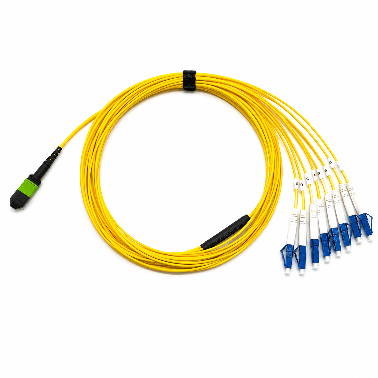
A breakout can connect a multifiber patching position to several individually addressable equipment ports without adding a cassette at the equipment end. This can reduce the number of intermediate components, but it transfers more responsibility to branch labeling, routing, and port-map control. Use it when the equipment layout is known and the individual legs can be routed without crowding the connector face.
Direct connection to parallel optics
Do not assume every parallel-optics port should be broken into duplex links. Start with the transceiver data sheet and identify which MPO positions carry transmit and receive lanes. A breakout is appropriate only when the receiving equipment expects those lanes as separate interfaces and the approved map preserves the required Tx-to-Rx relationship.
Test and monitoring equipment
Individually labeled branches can expose defined fiber positions to power meters, sources, switches, or monitoring channels. In this case, repeatable numbering matters more than a generic harness name. The branch labels, instrument channels, drawing, and test report should all use the same position convention.
Custom cabinet or device layout
A drawing-controlled hydra is useful when branch lengths, exit directions, connector types, or port order vary across a device face. Measure the physical route rather than using equal branch lengths by default. Extra length can obstruct airflow or create bend-control problems, while short legs can load the connector and make service difficult.
Control the branch design
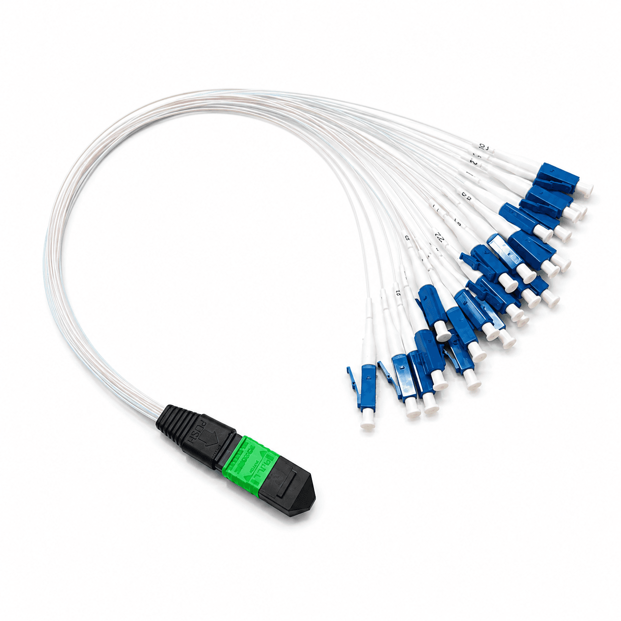
Once the assembly type is known, the branch design determines whether it can actually reach, fit, and remain serviceable at the equipment. The transition must protect the fibers as they leave the main cable, while each leg needs enough flexibility to reach its assigned port without transferring load to the connector.
Color coding and printed numbers serve different purposes. Fiber colors help identify positions during production and inspection; external branch labels give installers a stable port reference. Both should correspond to the approved mapping document, especially when the legs cross or are routed into separate equipment groups.
Branch interface
Name the exact connector at every branch and state simplex or duplex construction.
Branch quantity
Match physical legs to active positions; do not infer the count from the MPO shell alone.
Port map
Record how MPO positions map to numbered branches and equipment ports.
Fan-out length
Measure from the breakout transition to each connector reference point.
Leg protection
Select tubing, diameter, and bend control for the routing and handling conditions.
Identification
Define readable branch numbers, End A/End B labels, and any equipment-port references.
Example: translating an eight-branch layout into a drawing
Suppose End A is an MTP/MPO interface with eight active positions and End B consists of eight simplex equipment ports. The drawing should identify which MPO position becomes Branch 1, which becomes Branch 2, and so on through Branch 8. It should also state the viewing direction used to number the MPO positions.
If the equipment ports are arranged in two rows, equal branch lengths may not produce a clean installation. The upper and lower rows can require different leg lengths or routing groups. Record those dimensions individually and make the physical labels match the approved port sequence. This prevents an installer from having to infer mapping from cable reach.
Breakout cable RFQ information
A useful RFQ lets engineering reproduce the intended link without guessing. Attach a simple diagram even if some values remain open, and identify unresolved fields for review rather than substituting a generic catalog configuration. Use the complete MTP/MPO specification guide to review the parameters that apply beyond the breakout structure.
The quotation and approval drawing should use the same endpoint names, dimensions, and branch sequence. Any later change to equipment ports or routing should trigger a review of the map and fan-out dimensions.
- 01Simple link diagram and application
- 02End A multifiber interface and gender
- 03Branch connector type and quantity
- 04Active fiber positions and port map
- 05Fiber type and cable construction
- 06Overall length and fan-out lengths
- 07Branch numbering and label sequence
- 08Polarity or position-by-position mapping
- 09Test evidence and acceptance limits
- 10Quantity, destination, and delivery date
Related products
This product family is relevant when turning the breakout selection guidance into a defined cable configuration.
Frequently asked questions
Are harness, hydra, and fan-out cables the same?+−
The names overlap, but they are not reliable specifications by themselves. Harness and hydra usually describe an MTP/MPO-to-multiple-connector assembly, while fan-out describes the physical breakout construction. Always define the actual interfaces, branch count, dimensions, and port map.
When should I use a trunk instead of a breakout?+−
Use a trunk when both endpoints require multifiber MTP/MPO interfaces. Use a breakout when one multifiber interface must connect to individually addressable simplex or duplex ports.
Can branch numbers be assigned in any order?+−
They can be customized, but the sequence must match an approved position map. The drawing, labels, and test report should use the same numbering convention.
Is fan-out length the same as total cable length?+−
No. Overall length describes the assembly reference length, while fan-out length describes the individual legs after the breakout transition. Both measurement references should be stated on the drawing.
Does the cable name define polarity?+−
No. Harness, hydra, and fan-out describe structure, not the completed Tx-to-Rx mapping. Approve polarity from the complete channel or a position-by-position map.
References and supporting material
- ANSI/TIA-568.3-E — Optical Fiber Cabling and Components Standard.
- IEC 61754-7 — MPO connector-family interface standard.
- How to Choose the Right MTP® or MPO Cable Assembly
- MPO Polarity Explained: Type A, Type B, and Type C
- Custom Fiber Assembly RFQ Checklist
- Browse all CAIVALE product drawings