
On this page
Choose a fiber optic connector from the mating interface and the cable being terminated. Confirm connector family, fiber and polish, simplex or duplex format, cable or buffer diameter, boot, assembly method, and inspection requirements as one compatible termination.
A connector is not interchangeable simply because its ferrule fits the same fiber. The equipment port determines the connector family and polish, while the cable construction determines the rear body, crimp, boot, and strain-relief arrangement.
Start with the finished assembly rather than a loose connector photograph. Record what the connector mates with, what fiber or cable enters it, how it will be installed, and what evidence is required after termination.
Start with the mating interface and termination method
Identify the equipment, adapter, transceiver, instrument, or panel interface. The connector must match the mechanical coupling method, ferrule format, keying, polish, and port density of that interface.
Then define whether the connector will terminate 900 µm buffered fiber, simplex cable, duplex cable, or another approved cable construction. The rear components must grip and protect that exact diameter without placing load on the fiber.
Also state whether the requirement is for loose connector components, a field-installable termination, or a factory-assembled and tested cable. Those are different manufacturing scopes and should not share an incomplete part description.
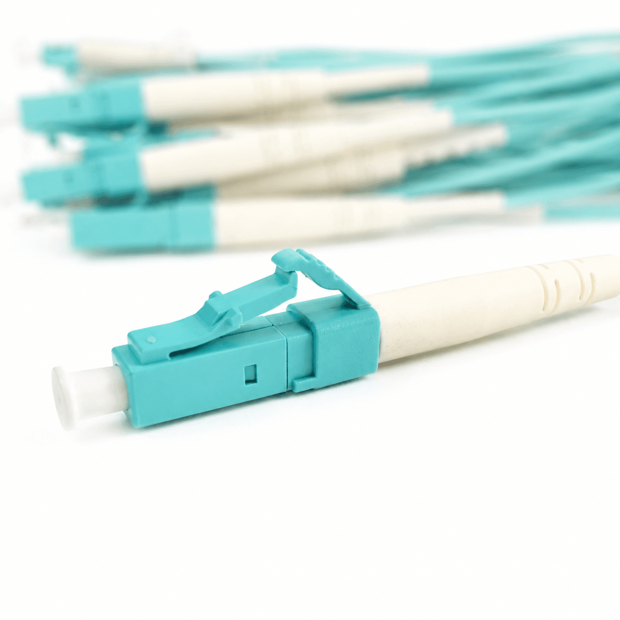
Compare connector families by the equipment interface
Use the equipment port as the controlling source. Density, coupling method, vibration, service access, and legacy compatibility help narrow the connector family.
| Connector | Typical decision context | Confirm before ordering |
|---|---|---|
| LC | Compact equipment and high-density patching | Simplex/duplex format, polish, latch and boot clearance |
| SC | Telecom, patch panels, FTTH, and distribution equipment | Simplex/duplex format, polish, housing and cable entry |
| FC | Threaded instrument, telecom, or vibration-sensitive interfaces | Polish, key width, body style, and tightening access |
| ST | Bayonet-style legacy, campus, or industrial equipment | Equipment compatibility, body style, and cable diameter |
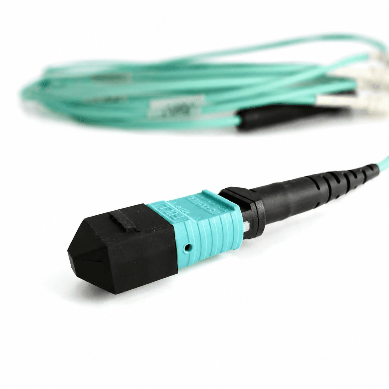
| MTP/MPO | Parallel or high-density multifiber interfaces | Fiber count, gender, key orientation, performance grade, and boot |
Control the fields behind the connector name
A usable connector description resolves both the optical interface and the mechanical termination.
Fiber and polish
Confirm single-mode or multimode compatibility and state UPC or APC where applicable. Do not treat connector housing color as the specification.
Connector format
State simplex, duplex, keyed, pinned, unpinned, or other format fields required by the connector family.
Cable or buffer diameter
Match the rear body, crimp, boot, and strain relief to the actual 900 µm buffer or cable diameter.
Boot and access
Choose standard, short, angled, pull-tab, or project-specific access based on the space behind the equipment port.
Assembly method
Define whether the connector is supplied as components or as part of a factory-terminated assembly.
Identification
Record housing, boot, clip, label, and packaging requirements without using color as a substitute for optical specifications.
Match the rear construction to the cable
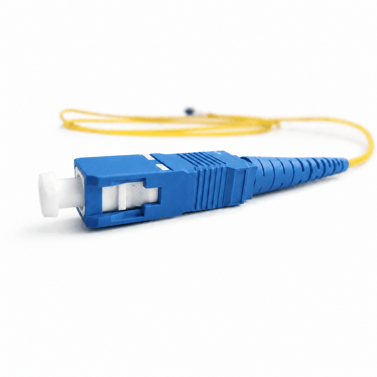
Connector selection often fails at the rear of the housing rather than at the ferrule. A boot designed for one cable diameter may not provide correct strain relief on another. Duplex clips, uniboot constructions, breakout legs, and tight-buffer terminations also require different component combinations.
Provide a cable cross-section or finished-cable reference when the construction is not standard. For factory assembly, keep the connector, cable, crimp, boot, and process together on one approved BOM or drawing.
If the connector will be installed in a dense panel, verify latch access, extraction clearance, bend radius, and the direction in which the boot exits the port.
Define termination and inspection evidence
The acceptance plan should match whether you are buying components or finished cable assemblies.
Common selection mistakes
- 01Ordering by connector family without stating polish
- 02Using housing color as the only fiber or polish definition
- 03Ignoring cable or buffer diameter
- 04Mixing component-only and finished-assembly requirements
- 05Omitting duplex clip or MTP/MPO gender and keying
- 06Selecting a boot that cannot be serviced in the equipment layout
Fiber optic connector RFQ checklist
Attach the equipment interface and cable construction if any field remains uncertain. A connector part description should be reproducible without relying on a catalog image.
- 01Application and mating equipment
- 02Connector family and format
- 03Fiber type and polish
- 04Simplex, duplex, fiber count, or gender where applicable
- 05Cable or buffer diameter
- 06Boot, clip, and housing requirements
- 07Component kit or finished-assembly scope
- 08Performance and inspection evidence
- 09Color, labels, and packaging
- 10Quantity, destination, and delivery date
Related products
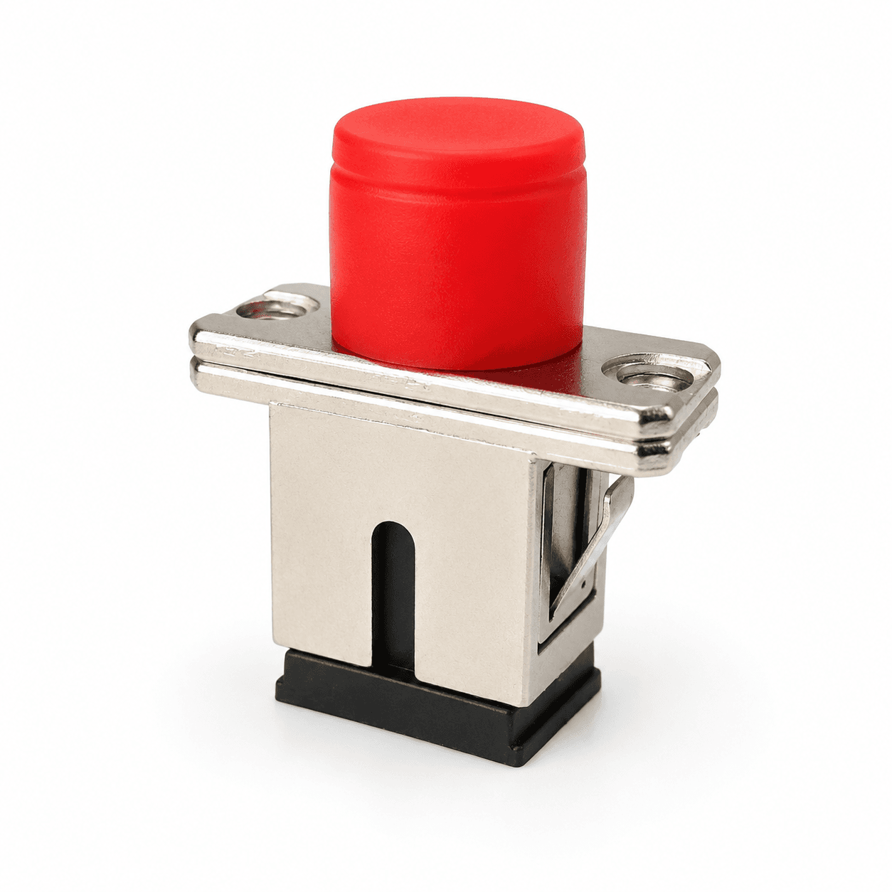
LC Fiber Optic Connector
Compact LC connectors for high-density singlemode and multimode assemblies.
SC Fiber Optic Connector
Push-pull SC connectors for telecom, FTTH, CATV, and optical distribution links.
MPO Fiber Optic Connector
MPO multifiber connectors for high-density trunks, modules, breakouts, and parallel-optics links.
Frequently asked questions
How do I choose between LC, SC, FC, and ST connectors?+−
Match the equipment interface first, then review density, coupling method, access, polish, and cable construction. The connector family cannot be chosen independently from the port it mates with.
Can connector color identify UPC or APC?+−
Color is a useful visual convention but should not be the sole purchasing definition. State UPC or APC explicitly and confirm the mating interface.
Why does cable diameter matter when buying a connector?+−
The rear body, crimp, boot, and strain relief must match the cable or buffer diameter. A mismatch can cause poor retention, fiber stress, or an incomplete assembly.
Is an MTP/MPO connector specified only by fiber count?+−
No. Confirm fiber count, gender, key orientation, performance grade, fiber type, cable construction, boot, and the completed polarity requirement.
What should be tested after connector termination?+−
Finished assemblies commonly require end-face inspection and optical testing. Define insertion loss, return loss where applicable, wavelength, report format, and any geometry evidence required by the project.
References and supporting material
- ANSI/TIA-568.3-E — Optical Fiber Cabling and Components Standard.
- IEC 61754 series — Fibre optic interconnecting devices and passive components.
- Fiber Optic Patch Cable Buying Guide
- Browse product drawings
- Reports & Compliance