
On this page
Start with the equipment interfaces at both ends. Then define fiber type, connector format, polish, simplex or duplex structure, jacket, cable diameter, length, and acceptance testing. Do not select a patch cable by connector name or jacket color alone.
A fiber patch cable is a complete interface between two known connection points. The connector at End A can differ from End B, and each end may impose its own polish, housing, density, and handling constraints.
A reliable selection process therefore moves from the physical link to the cable construction. Once the endpoints are confirmed, the remaining fields can be reviewed as one controlled configuration rather than a collection of independent options.
Start with both endpoints
Identify the equipment, adapter, transceiver, patch panel, or instrument at each end. Record the actual mating interface instead of assuming that both ends use the same connector.
Check whether the connection area limits connector width, latch access, boot length, bend radius, or finger clearance. A technically compatible connector can still be difficult to install if the cable and boot do not fit the equipment layout.
For hybrid cables, write End A and End B separately throughout the RFQ, drawing, labels, and test record.
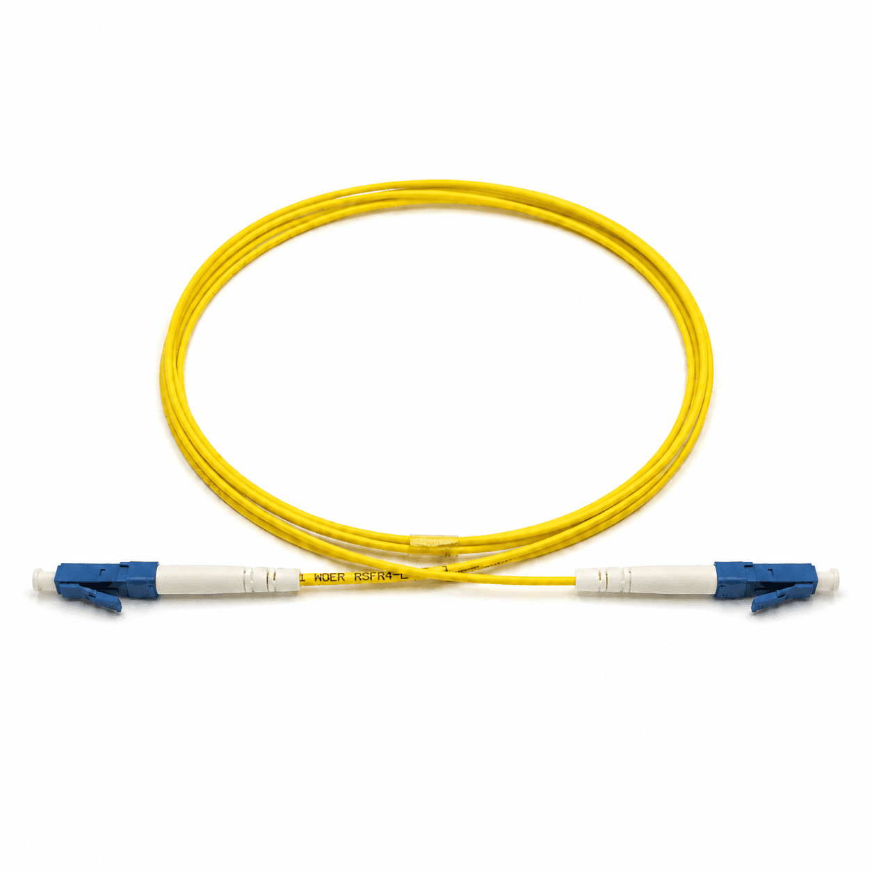
Choose the connector at each end
Connector names narrow the choice, but the format, polish, equipment clearance, and opposite endpoint complete the specification.
| Interface | Typical selection reason | Confirm before ordering |
|---|---|---|
| LC | High-density equipment and patching | Simplex or duplex format and latch clearance |
| SC | Patch panels, telecom, and distribution equipment | Simplex or duplex housing and polish |
| FC | Threaded equipment and instrument interfaces | Polish, key orientation, and tightening access |
| ST | Bayonet-style legacy or industrial interfaces | Exact equipment compatibility and available clearance |
| MU / E2000 | Equipment- or project-specific interfaces | Exact mating interface and polish |
| Hybrid | Different interfaces at End A and End B | Record each end independently |
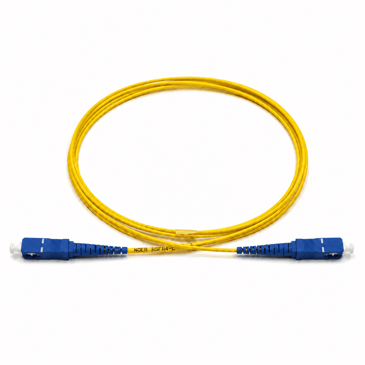
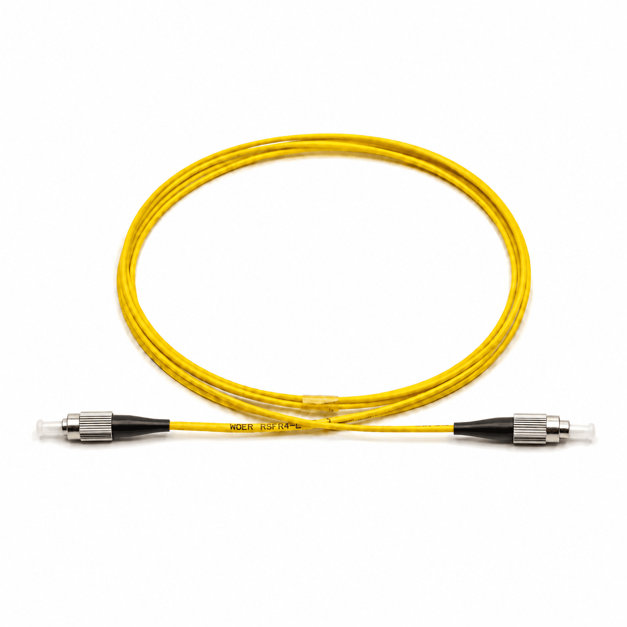
Select single-mode or multimode fiber
Match fiber type to the transceivers, wavelength, required reach, and installed link. The patch cable should not introduce a different fiber category simply because its jacket color looks familiar.
OS2 is commonly used in single-mode systems. OM1 through OM5 identify multimode categories with different system capabilities and compatibility considerations. Use the equipment and link design as the controlling source.
| Fiber | Common context | Main confirmation |
|---|---|---|
| OS2 | Single-mode links and long-reach systems | Transceiver, wavelength, and installed fiber |
| OM3 / OM4 | Multimode data center and enterprise links | Required speed, reach, and installed fiber |
| OM5 | Wideband multimode systems | Equipment and system compatibility |
| OM1 / OM2 | Existing legacy multimode networks | Compatibility with the installed link |
Confirm UPC or APC polish
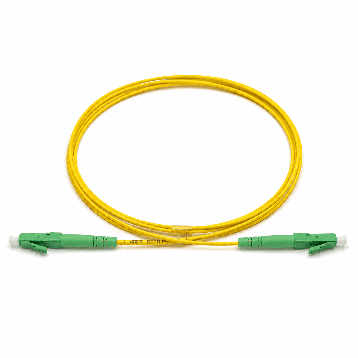
UPC and APC describe different end-face geometries. They are not general quality grades and should not be directly mated to one another.
Blue is commonly associated with UPC and green with APC, but color alone is not sufficient purchasing evidence. Confirm the polish required by the equipment or adapter at each endpoint and record it explicitly.
A hybrid patch cable can use different connector families at its two ends, but each polish still has to match the interface it mates with.
Choose the cable structure
Structure follows the number of optical paths and the way the equipment presents its ports. Duplex does not automatically define polarity, and fan-out needs additional branch information.
Simplex
One optical path is required
One fiber and the connector at each end
Duplex
A paired transmit/receive link is required
Pairing and A-to-B orientation
Uniboot duplex
Rack cable volume needs to be reduced
Polarity method and connector access
Fan-out
Multiple fibers need separate connectors
Fiber count, branch length, and labels
If an MTP/MPO interface breaks out to several independently routed ports, use the MTP/MPO breakout cable buying guide instead of duplicating the branch-selection process here.
Define jacket, diameter, boot, and length
PVC, LSZH, OFNR, and OFNP are not interchangeable descriptions. Record the installation space, project location, and required material or fire rating. Indoor, outdoor, armored, or pulling conditions may require a different cable construction.
Cable diameter and boot style affect rack density, bend control, connector access, strain relief, and cable management. Confirm whether the layout needs a standard, short, angled, or pull-tab boot and whether the available bend space supports the selected diameter.
State how length is measured, including the reference points, units, and tolerance. Allow for the physical route, bend radius, service loop, and equipment access rather than ordering from straight-line distance alone.
Record the measurement reference, not only the nominal length.
Specify performance and testing
Define the evidence needed to accept the finished cable. Depending on the project, that can include insertion loss, return loss, test wavelength, end-face inspection, interferometer evidence, serialized labels, and a test report. Avoid a request such as “low loss” without a scope or acceptance basis.
Common selection mistakes
- 01Selecting from the connector name without checking both equipment interfaces.
- 02Using jacket or connector color as the only evidence of fiber type or polish.
- 03Mating UPC and APC interfaces directly.
- 04Omitting simplex, duplex, or transmit/receive orientation.
- 05Choosing a jacket without confirming the installation environment or local requirement.
- 06Providing a nominal length without a measurement reference.
- 07Requesting “low loss” without defining the test wavelength, scope, or evidence.
Build the complete ordering description
Use a repeatable field order so both endpoints and the cable construction remain visible:
Example format: Duplex LC/UPC to LC/UPC, OS2, LSZH, 2.0 mm, 3 m, 100% insertion-loss tested, 200 pcs. This illustrates the description format only; it is not a default recommendation.
Fiber patch cable RFQ checklist
Mark unresolved fields for engineering review instead of substituting an assumed configuration. Keep the quotation, approval drawing, labels, and test report aligned to the same description.
- 01Application and link diagram
- 02End A connector, format, and polish
- 03End B connector, format, and polish
- 04Fiber type
- 05Simplex, duplex, uniboot, or fan-out structure
- 06Jacket material and required fire rating
- 07Cable diameter and boot style
- 08Length, units, and measurement reference
- 09Color, labels, and packaging
- 10Test scope and report requirements
- 11Quantity, destination country, and delivery date
Related product
Standard Fiber Patch Cable
Configurable fiber patch cable for LC, SC, FC, ST, MU, E2000, and hybrid connector combinations.
Frequently asked questions
How do I choose between single-mode and multimode patch cables?+−
Match the patch cable to the transceivers, wavelength, reach, and installed fiber in the complete link. Do not choose from jacket color alone.
Can UPC and APC connectors be connected directly?+−
No. UPC and APC end-face geometries are different and should not be directly mated. Confirm the polish required by each equipment or adapter interface.
Should I use simplex or duplex fiber patch cables?+−
Use simplex for one optical path and duplex when the equipment requires a paired transmit/receive connection. Confirm the equipment ports and the required pair orientation.
What is the difference between PVC, LSZH, OFNR, and OFNP jackets?+−
They describe different material or installation-rating requirements and are not interchangeable labels. Specify the installation location and the rating required by the project or applicable rules.
How should fiber patch cable length be measured?+−
State the reference points, units, and allowed tolerance. Connector-end reference length is clearer than a nominal number with no measurement definition.
What information is required for a fiber patch cable quotation?+−
Provide both interfaces, polish, fiber type, cable structure, jacket, diameter, boot, length, labels, testing, quantity, destination, and delivery requirement.
References and supporting material
- ANSI/TIA-568.3-E — Optical Fiber Cabling and Components Standard.
- IEC 61754 series — Fibre optic interconnecting devices and passive components.
- Standard Fiber Patch Cable
- Browse CAIVALE product drawings
- Reports & Compliance
- MTP/MPO Breakout Cable Buying Guide