
On this page
Choose an MTP/MPO plug-and-play module from the complete channel. Define the rear trunk interface, front-port connector format, fiber count, Base-8 or Base-12 architecture, polarity and position map, panel fit, loss budget, labels, and test evidence together.
A cassette module is a controlled transition between a rear multifiber interface and front equipment or patching ports. It must preserve the intended fiber map while fitting the rack or panel and remaining within the channel loss budget.
Do not select a module from front-port count alone. The rear trunk, active fiber positions, internal mapping, front-port format, patch cords, and transceivers form one system.
Start with the channel architecture
Draw the path from the rear trunk through the module to the front patch cords and equipment. Record every MTP/MPO interface, adapter, cassette, and duplex or simplex connection that can change the completed position map.
Identify whether the system is Base-8, Base-12, or another approved architecture. A 12-position shell does not prove that all positions are active, and a front-port count does not reveal how fibers are mapped internally.
Confirm the MTP/MPO gender and key orientation required by the mating trunk, then define the front connector family, polish, port count, and label sequence.
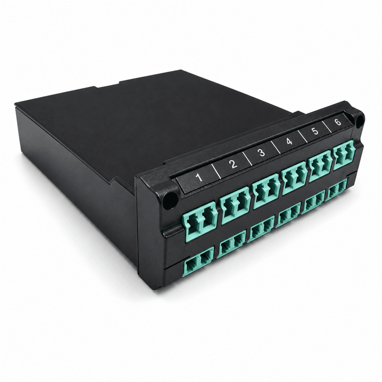
Base-8 or Base-12: control the active positions
Architecture is a channel decision. Use transceiver lanes, trunk construction, cassette mapping, and future migration plan as the controlling evidence.
| Decision | Base-8 direction | Base-12 direction |
|---|---|---|
| Active fibers | Eight active positions organized for the approved application | Up to twelve positions depending on the approved link |
| Front presentation | Often four duplex channels per eight active fibers | Often six duplex channels per twelve active fibers |
| Trunk compatibility | Requires the matching Base-8 trunk and map | Requires the matching Base-12 trunk and map |
| Migration planning | Can align with selected parallel-optics paths | Can support established 12-fiber structured cabling |
| Approval evidence | Position map for every active lane | Position map for every active and unused position |
Define every interface and mapping boundary
The module should be reviewed as a mapping device, a mechanical component, and an optical-loss contributor.
Rear MTP/MPO interface
State fiber count, gender, key orientation, fiber type, polish, and the trunk that mates with it.
Front ports
Define LC, SC, or other approved format, simplex/duplex presentation, polish, count, and numbering.
Internal position map
Approve how each rear position becomes a front port and how transmit/receive orientation is preserved.
Panel footprint
Confirm module dimensions, mounting points, orientation, panel type, and front/rear access.
Cable management
Allow space for rear trunk bend radius, front patch cords, latches, labels, and service loops.
Identification
Use module ID, rear-port ID, front-port sequence, polarity, and test-report references consistently.
Fit the module into the rack and cable route
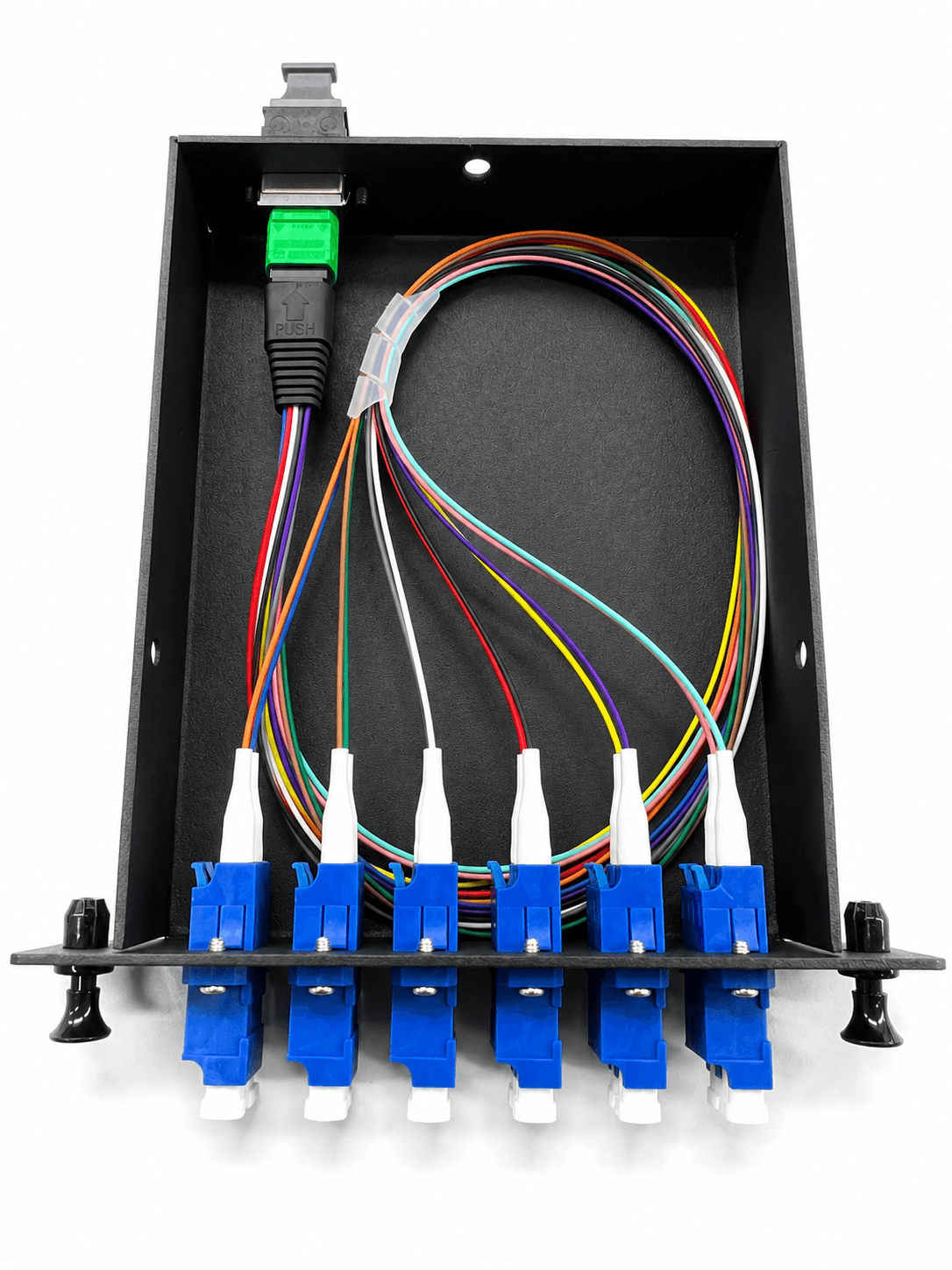
Confirm the module footprint against the actual panel rather than assuming a universal cassette size. Record orientation, mounting method, insertion direction, retention, and the number of module positions available in the enclosure.
Rear depth and bend space matter as much as the front face. Check the trunk connector body, pulling direction, bend radius, strain relief, and clearance from doors, trays, fans, and adjacent modules.
At the front, verify patch-cord boot clearance, latch access, port labeling, and whether technicians can clean and inspect connectors without removing neighboring modules.
Build the optical loss and test boundary
The cassette adds internal connections to the channel. Define what is tested at the module level and what is accepted only after the complete link is installed.
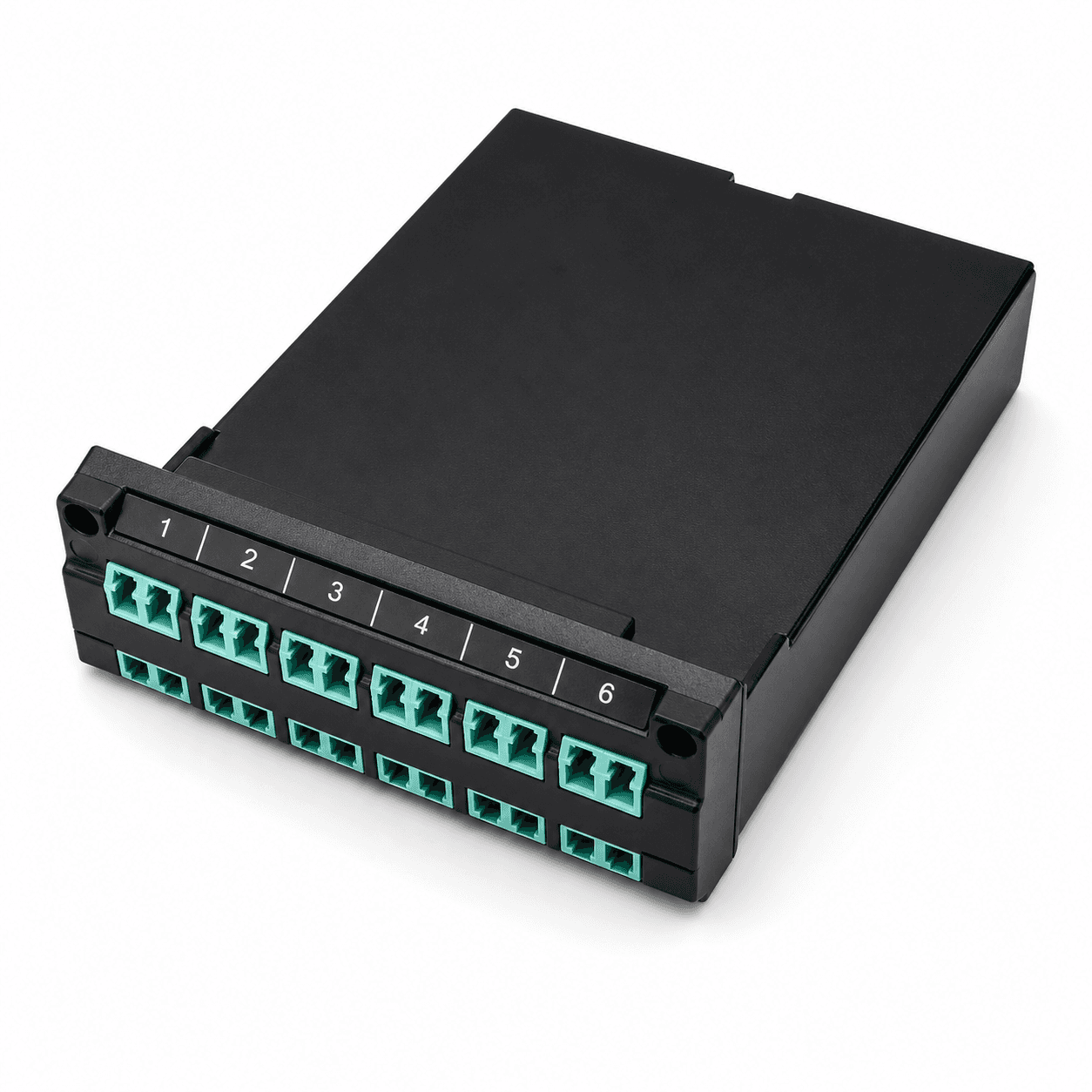
Common selection mistakes
- 01Selecting by front-port count without tracing the rear positions
- 02Mixing Base-8 and Base-12 components without an approved map
- 03Assuming the cable name defines completed polarity
- 04Ignoring MTP/MPO gender or key orientation
- 05Omitting module footprint and rear cable clearance
- 06Building a loss budget without every mated connection
Plug-and-play module RFQ checklist
Attach a channel diagram and panel reference. The quotation and test report should use the same rear position map and front-port numbering.
- 01Application and complete channel diagram
- 02Base-8, Base-12, or approved architecture
- 03Rear MTP/MPO interface, gender, and key orientation
- 04Fiber type and active positions
- 05Front connector format, polish, and port count
- 06Internal polarity and position map
- 07Module dimensions, orientation, and panel fit
- 08Loss budget and test requirements
- 09Port labels, module ID, and packaging
- 10Quantity, destination, and delivery date
Related products
MTP® or MPO Rack & Mini Module
Plug-and-play rack and mini module system for high-density MTP® or MPO to LC, SC, FC, ST, MU, or E2000 deployment.
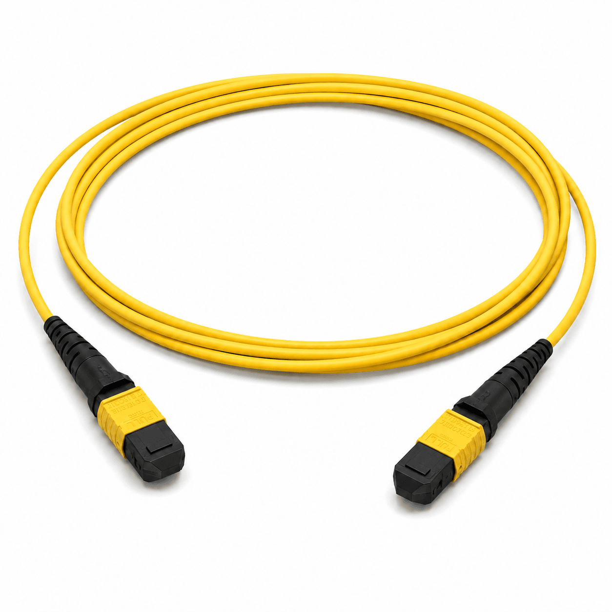
Custom MTP®/MPO Trunk Cable Assemblies
MTP® or MPO standard jumper and trunk cable assemblies with standard, pulling eye, pulling grip, or pulling sock installation options.
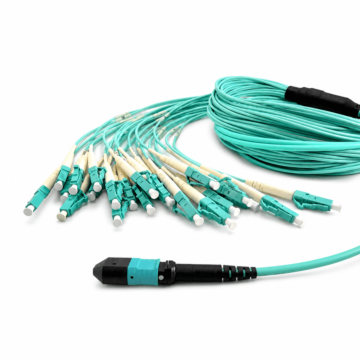
MTP® or MPO Hydra & Harness
MTP® or MPO hydra and harness breakout cable assemblies to LC, SC, FC, ST, MU, E2000, or MT-RJ connectors.
Frequently asked questions
How do I choose between Base-8 and Base-12 modules?+−
Match the transceiver application, active fiber positions, trunk architecture, internal cassette map, and migration plan. Do not infer architecture from the MTP/MPO shell alone.
Does the module determine polarity by itself?+−
No. Completed polarity depends on the trunk, module mapping, adapters, patch cords, and equipment interfaces. Approve the complete Tx-to-Rx path.
How many duplex ports should a module have?+−
The count follows the active fibers and approved architecture. Eight active fibers can present four duplex channels, while twelve active fibers can present six, but the actual map must be documented.
What dimensions are needed for panel compatibility?+−
Confirm module width, height, depth, mounting points, orientation, insertion direction, rear connector clearance, front boot clearance, and enclosure capacity.
What should the module test report include?+−
Define position-by-position continuity, insertion loss, return loss where applicable, polarity verification, end-face inspection, and module or port identification.
References and supporting material
- ANSI/TIA-568.3-E — Optical Fiber Cabling and Components Standard.
- IEC 61754 series — Fibre optic interconnecting devices and passive components.
- MTP/MPO Cable Assembly Buying Guide
- MPO Polarity: Type A, Type B, and Type C
- Browse product drawings